This HW covers CB chapter 5 or LT chapter 5.
The homework consists of 10 problems for a total of 65 pts.
Please begin your question with the problem number you are asking about.
Cengel & Boles, Ch 5:
5.35 - Adiabatic Steam Nozzle - 5 pts
5.54 - Adiabatic Gas Turbine - 5 pts
5.112 - Steam Flow in a HEX Tube - 5 pts
5.138 - Filling a Balloon with Helium - 10 pts
5.142 - Charging a Cylinder with a Spring-Loaded Piston - 8 pts
Special Problems
WB-1 - Effluent Pressure in a Non-Adiabatic Steam Diffuser - 5 pts
WB-2 - Steady-State, Polytropic Air Compressor - 5 pts
WB-3 - Analysis of a Two-Stage, Adiabatic Turbine - 6 pts
WB-4 - Analysis of an Adiabatic Steam De-Superheater - 8 pts
WB-5 - Waste Heat Steam Generator - 8 pts
Wednesday, April 13, 2011
Wednesday, April 06, 2011
ENGR 224 - HW #2
This HW covers CB chapters 2, 4 and parts of 6 or LT chapters 3 & 4.
The homework consists of 16 problems for a total of 57 pts.
Please begin your question with the problem number you are asking about.
Cengel & Boles: Ch 3:
3.26(2pts) -
Use either the NIST Webbook or the Thermal/Fluids Toolbox (TFT) Excel plug-in.
Use the default reference state for both the NIST and TFT.
3.29E(2pts) -
Use either the NIST Webbook or the Thermal/Fluids Toolbox (TFT) Excel plug-in.
Use the default reference state for both the NIST and TFT.
Cengel & Boles: Ch 4:
4.8(6pts) : W ~ -22 kJ
4.42(5pts) : Q ~ 12750 kJ
4.59E(4pts) : See textbook
4.60(4pts) : ΔU ~ 6200 Btu/lbm
Special Problems
WB-1(5pts) : ΔHvap ~ 575 to 600 Btu/lbm
WB-2(8pts) : ΔH14 ~ 9900 J
WB-3(6pts): Q23 ~ -85 Btu , Wcycle ~ -20 Btu
WB-4(3pts) : q ~ -97 Btu/h-ft2
WB-5(3pts) : Q ~ 3500 W
WB-6(3pts) : Lins ~ 6 cm
WB-7(3pts) : Wb ~ 350 kJ
Cengel & Boles: Ch 6: 6.23(2pts), 6.41(2pts), 6.55(2pts). These problems should be pretty easy.
Friday, March 25, 2011
ENGR 224 - Thermodynamics at GRCC
Welcome to the Thermodynamics course at Green River Community College in Auburn, WA, USA.
Feel free to post any general questions about the course as comments on this blog entry.
I have created a blog entry for each chapter we will cover in this course. If you think your question applies to a specific chapter, then please post your question as a comment on the appropriate blog entry.
I have created a blog entry for each of the 7 HW assignments in the course. If you have a question about a problem in the HW, please post it as a comment on the appropriate blog entry. Be sure to state which problem number your question refers to !
You can post your questions using your Google ID or a crazy fake name or your real name or you can post anonymously. Whatever makes you happy. Just don't hesitate to ASK !
Remember...
"It's not a miracle, mother, it's thermodynamics !"
- Harrison Ford in Mosquito Coast
ENGR 224 - HW #1
This HW covers CB chapters 1 & 3 or LT chapters 1 & 2.
The homework consists of 15 problems for a total of 71 pts.
Please begin your question with the problem number you are asking about.
Cengel & Boles: Ch 1: 7E(3pts), 11E(4pts), 37E(2pts), 41E(3pts), 78(6pts)
WB-1 (4pts) , WB-2 (5pts)
Cengel & Boles: Ch 3: 26(4pts), 29E(4pts), 37E(5pts), 53(6pts), 66(4pts),
83(6pts) - Assume that the air in the tire behaves as an ideal gas, but then check the validity of this assumption.
WB-3 (10pts) , WB-4 (5pts)
Friday, March 18, 2011
HW 7B-16 - Isentropic Compression of High Quality Steam - 5 pts
Steam is compressed isentropically to a final pressure of 5 MPa. The steam is initially at 25oC and has a quality of 91%. How much work does this process require, in kJ/kg, if the process takes place in... (a) A closed system? (b) An open system ? (c) Explain why the answers to parts (a) and (b) are not the same.
For hints and answers visit:
http://www.LearnThermo.com/T1-tutorial/ch07/lesson-B/pg20.php#P7B16
For hints and answers visit:
http://www.LearnThermo.com/T1-tutorial/ch07/lesson-B/pg20.php#P7B16
Wednesday, March 16, 2011
HW 7B-15 - Heat and Work in an Isothermal Expansion of Steam - 5 pts
Saturated water vapor is contained in a piston-and-cylinder device that is positioned in a constant-temperature bath at 250oC. The 5.7 kg of steam inside the cylinder expands reversibly and isothermally to a final pressure of 1.2 MPa. Determine the heat transferred between the constant-temperature bath and the water inside the cylinder as well as the work done by the H2O inside the cylinder during this process.
For hints and answers visit: http://www.LearnThermo.com/T1-tutorial/ch07/lesson-B/pg20.php#P7B15
For hints and answers visit: http://www.LearnThermo.com/T1-tutorial/ch07/lesson-B/pg20.php#P7B15
HW 7B-14 - Reversible Compression of Steam in a Piston-and-Cylinder Device - 4 pts
Superheated steam is reversibly compressed from 200 kPa to 1.4 MPa in a well-insulated piston-and-cylinder device. The cylinder initially contains 0.175 m3 of steam at 250°C. Determine the final temperature of the steam and the work done on the steam during this process.
For hints and answers visit: http://www.LearnThermo.com/T1-tutorial/ch07/lesson-B/pg20.php#P7B14
For hints and answers visit: http://www.LearnThermo.com/T1-tutorial/ch07/lesson-B/pg20.php#P7B14
HW 7B-13 - Minimum Power Required for Adiabatic Compression of R-134a - 4 pts
An adiabatic compressor is used to increase the pressure from 105 kPa to 1.25 MPa in a stream of R-134a with a volumetric flow rate of 1800 L/min. Determine the minimum power that must be supplied to the compressor.
For hints and answers visit: http://www.LearnThermo.com/T1-tutorial/ch07/lesson-B/pg20.php#P7B13
For hints and answers visit: http://www.LearnThermo.com/T1-tutorial/ch07/lesson-B/pg20.php#P7B13
HW 7B-12 - Reversible Expansion of R-134a in a Piston-and-Cylinder Device - 4 pts
The refrigerant R-134a expands reversibly from 2 MPa to 500 kPa in an insulated piston-and-cylinder device. The cylinder initially contains 15 L of R-134a with a quality of 1.0. Determine the final temperature of the R-134a in the cylinder and the work done during this process.
For hints and answers visit: http://www.LearnThermo.com/T1-tutorial/ch07/lesson-B/pg20.php#P7B12
For hints and answers visit: http://www.LearnThermo.com/T1-tutorial/ch07/lesson-B/pg20.php#P7B12
HW 7B-11 - Entropy Change and Boundary Work for the Isobaric Expansion of Water - 10 pts
Electrical work is done by an electrical resistance heater on H2O contained in an insulated piston-and-cylinder device. The cylinder initially contains 2.4 L of saturated liquid water at a pressure of 500 kPa. Assuming the piston moves freely, determine the total entropy change of the H2O during a process in which 1875 kJ of heat is transferred into the water. What is the boundary work for this process?
For hints and answers visit: http://www.LearnThermo.com/T1-tutorial/ch07/lesson-B/pg20.php#P7B11
For hints and answers visit: http://www.LearnThermo.com/T1-tutorial/ch07/lesson-B/pg20.php#P7B11
HW 7B-10 - Isobaric Condensation of R-134a - 5 pts
The refrigerant R-134a is cooled in a piston-and-cylinder device from 190°F to 75°F. The piston moves freely and the initial pressure is 200 psia. Determine the specific entropy change of the refrigerant, the work per lbm and heat transfer per lbm during this process.
For hints and answers visit:
http://www.LearnThermo.com/T1-tutorial/ch07/lesson-B/pg20.php#P7B10
For hints and answers visit:
http://www.LearnThermo.com/T1-tutorial/ch07/lesson-B/pg20.php#P7B10
Tuesday, March 15, 2011
HW 7B-9 - Expansion of Water into a Vacuum - 5 pts
A rigid tank is divided into two equal parts by a wall. One part of the tank contains 0.74 kg of water at 100 kPa and 25°C. The other part is a perfect vacuum. The wall is now removed and the water expands to fill the entire tank. A thermocouple indicates that the final equilibrium temperature of the H2O in the tank is 50oC. Determine the entropy change of water and the total heat transfer to the system during this process.
For hints and answers visit:
http://www.LearnThermo.com/T1-tutorial/ch07/lesson-B/pg20.php#P7B9
For hints and answers visit:
http://www.LearnThermo.com/T1-tutorial/ch07/lesson-B/pg20.php#P7B9
HW 7B-8 - Vaporization of Water in a Rigid Tank - 5 pts
An electric resistance heater is used to heat the contents of an insulated rigid tank that holds 23.1 kg of H2O. Initially, the pressure in the tank is 150 kPa and 44% of the mass inside the tank is saturated liquid and the remaining 56% is saturated vapor. Power is applied to the heater until all of the H2O in the tank is saturated vapor. Determine the entropy change of the H2O and the total of heat transfer during this process.
For hints and answers visit:
http://www.LearnThermo.com/T1-tutorial/ch07/lesson-B/pg20.php#P7B8
For hints and answers visit:
http://www.LearnThermo.com/T1-tutorial/ch07/lesson-B/pg20.php#P7B8
HW 7B-7 - Isentropic Expansion of R-134a - 4 pts
7-38E R-134a expands reversibly and adiabatically in a piston-and-cylinder device from 80 psia and 120°F to 5 psia. If the cylinder contains 17.4 lbm of R-134a, what are the total work done by the system during this process and final temperature of the R-134a ?
For hints and answers visit:
http://www.LearnThermo.com/T1-tutorial/ch07/lesson-B/pg20.php#P7B7
For hints and answers visit:
http://www.LearnThermo.com/T1-tutorial/ch07/lesson-B/pg20.php#P7B7
HW 7B-6 - Isentropic Compression of Water Vapor - 3 pts
An isentropic compressor takes in H2O at 105 kPa and delivers it at 450 kPa. If the temperature of the feed is 180°C, determine the temperature and specific enthalpy of the H2O at the compressor outlet.
For hints and answers visit:
http://www.LearnThermo.com/T1-tutorial/ch07/lesson-B/pg20.php#P7B6
For hints and answers visit:
http://www.LearnThermo.com/T1-tutorial/ch07/lesson-B/pg20.php#P7B6
HW 7B-5 - Entropy Change for an Isobaric Heating Process - 4 pts
A piston-and-cylinder device holds 9.7 lbm of water at 250 psia in a volume of 3.6 ft3. Heat is added to the water until the temperature reaches 425oF. During this process, the pressure in the cylinder remains constant because the piston moves freely. Determine the change in the entropy on the water in Btu/oR.
For hints and answers visit:
http://www.LearnThermo.com/T1-tutorial/ch07/lesson-B/pg20.php#P7B5
For hints and answers visit:
http://www.LearnThermo.com/T1-tutorial/ch07/lesson-B/pg20.php#P7B5
Wednesday, March 09, 2011
HW 7B-4 - Power Output of an Isentropic Turbine - 4pts
An isentropic turbine produces shaft work as R-134a at 275 psia and 225°F expands through the turbine and exits at 35°F. Assuming the turbine is adiabatic, determine the power output of the turbine per lbm of R-134a.
For hints and answers visit:
http://www.LearnThermo.com/T1-tutorial/ch07/lesson-B/pg20.php#P7B4
For hints and answers visit:
http://www.LearnThermo.com/T1-tutorial/ch07/lesson-B/pg20.php#P7B4
HW 7B-3 - Entropy Changes Associated with the Evaporator of a Refrigerator - 4 pts
A refrigerator using R-134a as the refrigerant removes 200 kJ of heat from its refrigerated space. This heat is absorbed by a mixture of saturated liquid and saturated vapor that enters the evaporator at a pressure of 175 kPa. The R-134a leaves the evaporator as a saturated vapor. Determine...
a.) ... the entropy change of the R-134a,
b.) ... the entropy change of the refrigerated space assuming its temperature remains constant at -10°C,
c.) ... the entropy change of the universe for this process.
For hints and answers visit:
http://www.LearnThermo.com/T1-tutorial/ch07/lesson-B/pg20.php#P7B3
Tuesday, March 08, 2011
HW 7B-2: Rate of Entropy Increase for a Heat Transfer Process
LearnThermo.com Homework Problem 7B-2
A hot reservoir at 944 K transfers heat to a cold reservoir at 298 K. If the rate of heat transfer is 25 kW,determine the rate at which the entropy of the two reservoirs combined changes (in kW/K) and determine if the second law is satisfied.
For hints and answers visit:
http://www.LearnThermo.com/T1-tutorial/ch07/lesson-B/pg20.php#P2
HW 7B-1: Entropy Change for a Heat Transfer Process
LearnThermo.com Homework Problem 7B-1
Calculate the entropy change of each reservoir when 1000 kJ of heat is transferred directly from a hot reservoir at 1000 K to a cold reservoir at 400 K. Calculate the entropy change of the universe for this process. Does this process violate the principle of increasing entropy?
For hints and answers visit:
http://www.LearnThermo.com/T1-tutorial/ch07/lesson-B/pg20.php#P1
Friday, December 12, 2008
TE 303 - Please give Dr.B some feedback about Thermo-CD
Well, the final is over and the holidays are almost here. I hope you had a great semester and learned a lot.
If you would be so kind as to share your opinions about Thermo-CD or ideas about how I could improve the program or workbook, that would be greatly appreciated. You can make your comments anonymously, but they would be more credible if you chose to give your name. Whether you give your name or not is up to you. I will NOT contact you in either case. You can always send questions or comments directly to me if you prefer: Dr.B@LearnThermo.com
Best of luck to all of you in the years ahead !
Happy Holidays,
Dr. B
Wednesday, December 03, 2008
TE 303 - HW #8, P1 - Inventor Claim for Silicon Chip - 20 pts
An inventor claims to have created a silicon chip whose surface temperature is no more than 60 °C. The silicon chip has dimensions of 5 mm on each side with a 1 mm thickness, and is embedded in a ceramic substrate. At steady state, the chip has an electrical power input of 0.225 W. The top surface of the chip is exposed to a coolant whose temperature is 20 °C. The heat transfer coefficient for convection (h) between the coolant and chip is 105 W/m2•K. Evaluate the inventor's claim using the following:
a.) First Law Energy Balance, assuming that the heat transfer by conduction between the chip and substrate is negligible.
b.) Second Law Energy Balance: Calculate entropy generation.
In your analysis section, be sure to comment on what is the main source of entropy generation in this system.
No old comments.
TE 303 - HW #8, P2 - Maximum Work From an Adiabatic Turbine - 10 pts
Steam enters an adiabatic turbine at 800 psia and 900oF and leaves at a pressure of 40 psia. Determine the maximum amount of work that can be delivered by this turbine.
No old comments.
No old comments.
TE 303 - HW #8, P3 - Lost Work in a Heat Exchanger - 15 pts
A well-insulated shell-and-tube heat exchanger is used to heat water (CP = 4.18 kJ/kg-K) in the tubes from 20oC to 70oC at a rate of 4.5 kg/s. Heat is supplied by hot oil (CP = 2.30 kJ/kg-K) that enters the shell side at 170oC at a rate of 10 kg/s.

Disregarding any heat loss from the heat exchanger, determine...
a.) The exit temperature of the oil.
b.) The rate of entropy generation in the heat exchanger.
c.) The rate at which work is lost due to the irreversible nature of heat transfer in this process in kW. Assume the surroundings are at 20oC.
3 Old Comments
TE 303 - HW #8, P4 - Entropy Generation and Lost Work in a Nozzle - 20 pts
Oxygen, O2, enters a nozzle operating at steady-state at 3.8 MPa, 387oC and 10 m/s. At the nozzle exit, the conditions are 150 kPa, 37oC and 790 m/s.
a.) For a system that encloses the nozzle only, determine the heat transfer (kJ/kg) and the change in specific entropy (kJ/kg-K), both per kg of oxygen flowing through the nozzle. What additional information would be required to evaluate the rate of entropy production in this process ?
b.) Using an enlarged system boundary that includes the nozzle and a portion of its immediate surroundings, evaluate the rate of entropy generation (kJ/kg-K) and the rate of lost work (kJ/kg), both per kg of oxygen flowing through the nozzle. Assume that heat exchange at the enlarged system boundary takes place at the ambient temperature, 20oC.
Treat O2 as an ideal gas with variable heat capacities. Verify that the ideal gas assumption is valid.
2 Old Comments
TE 303 - HW #8, P5 - Entropy Balance for a Power Plant - 25 pts
The figure to the right shows a simple vapor power plant operating at steady state with water as the working fluid. Data at key locations are given in the figure. The mass flow rate of the water circulating through the components is 109 kg/s. Stray heat transfer and kinetic and potential energy effects can be ignored.

Determine the following:
a.) The mass flow rate of the cooling water, in kg/s.
b.) The thermal efficiency.
c.) The rates of entropy production, each in kW/K, for the turbine, condenser, and pump.
In your analysis section, place the components in rank order, beginning with the component contributing most to inefficient operation of the overall system.
No old comments.
Thursday, November 13, 2008
TE 303 - HW #7, P1 - The Increase of Entropy - 15 pts
a.) Will the entropy of steam increase, decrease or remain the same as it flows through a real adiabatic turbine ?
b.) Will the entropy of the working fluid in an ideal Carnot Cycle increase, decrease or remain the same during the isothermal heat addition process ?
c.) Steam is accelerated as it flows through a real, adiabatic nozzle. Will the entropy of the steam at the nozzle exit be greater than, equal to or less than the entropy at the nozzle inlet ?
3 old comments
TE 303 - HW #7, P2 - Efficiency of an Int. Rev. HE with Multiple Heat Transfers - 10 pts
A system executes a power cycle while receiving 750 kJ by heat transfer at 1500 K and rejecting 100 kJ of heat at 500 K. A heat transfer from the system also occurs at 1000 K. There are no other heat transfers. If no internal irreversibilities exist in this system, determine the thermal efficiency of this cycle.
No old comments.
No old comments.
TE 303 - HW #7, P3 - ΔSSys, ΔSRes, and ΔSUniv, for a H.T. Process - 15 pts
During the isothermal heat addition process of a Carnot Cycle, 900 kJ of heat is added to the working fluid from a source at 400oC. Determine:
a.) the entropy change of the working fluid
b.) the entropy change of the heat source
c.) the total entropy change of the universe for this process.
1 old comment
a.) the entropy change of the working fluid
b.) the entropy change of the heat source
c.) the total entropy change of the universe for this process.
1 old comment
TE 303 - HW #7, P4 - Specific Entropy Change Using Tabluar Data - 16 pts
Using the appropriate table, determine the change in specific entropy in kJ/kg-K for:
a.) Water: P1 = 10 MPa, T1 = 400 degC and P2 = 10 MPa, T2 = 100 degC.
b.) R-134a: H1 = 211.44 kJ/kg, T1 = - 40 degC and P2 = 5 bar, x2 = 1.0.
c.) Air (IG): T1 = 7 degC, P1 = 2 bar and T2 = 327 degC, P2 = 1 bar.
d.) Hydrogen (H2, IG): T1 = 727 degC, P1 = 1 bar and T2 = 25 degC, P2 = 3 bar.
4 old comments
TE 303 - HW #7, P5 - DSUniv Upon Quenching an Iron Block - 20 pts
A 12 kg iron block initially at 350 degC is quenched in an insulated tank that contains 100 kg of water at 22 degC. Assuming the water that vaporizes during the process condenses back into the liquid phase inside the tank, determine the entropy change of the universe for this process.
6 old comments
6 old comments
TE 303 - HW #7, P6 - DS for Heat Transfer to R-134a in a Rigid Tank - 18 pts
A 0.5 m3 rigid tank contains R-134a initially at 200 kPa and 40% quality. Heat is transferred to the refrigerant from a source at 35oC until the pressure rises to 400 kPa. Determine…
a.) The entropy change of the R-134a.
b.) The entropy change of the heat source.
c.) The entropy change of the universe for this process.
2 old comments
a.) The entropy change of the R-134a.
b.) The entropy change of the heat source.
c.) The entropy change of the universe for this process.
2 old comments
Monday, November 03, 2008
TE 303 - HW #6, P1 - "Show That" Using the K-P Statement of the 2nd Law - 10 pts
Using the Kelvin-Planck statement of the 2nd Law, demonstrate the following corollaries.
a.) The coefficient of performance (COP) of an irreversible heat pump cycle is always less than the COP of a reversible heat pump when both heat pumps exchange heat with the same two thermal reservoirs.
b.) All reversible heat pump cycles exchanging heat with the same two thermal reservoirs have the same COP.
8 Old Comments
TE 303 - HW #6, P2 - Rev., Irrev. and Impossible Refrigeration Cycles - 16 pts
A refrigeration cycle operating between two reservoirs receives QC from a cold reservoir at TC = 250 K and rejects QH to a hot reservoir at TH = 300 K. For each of the following cases, determine whether the cycle is reversible, irreversible or impossible.
a.) QC = 1000 kJ and Wcycle = 400 kJ
b.) QC = 1500 kJ and QH = 1800 kJ
c.) QH = 1500 kJ and Wcycle = 200 kJ
d.) COP = 4
No Old Comments.
a.) QC = 1000 kJ and Wcycle = 400 kJ
b.) QC = 1500 kJ and QH = 1800 kJ
c.) QH = 1500 kJ and Wcycle = 200 kJ
d.) COP = 4
No Old Comments.
TE 303 - HW #6, P3 - A Reversible HE Used to Drive a Reversible Heat Pump - 10 pts
A reversible power cycle receives QH from a reservoir at TH and rejects QC to a reservoir at TC. The work developed by the power cycle is used to drive a reversible heat pump that removes Q'C from a reservoir at T'C and rejects Q'H to a reservoir at T'H.
a.) Develop an expression for the ratio Q'H / QH in terms of the temperatures of the four reservoirs.
b.) What must be the relationship of the temperatures TH, TC, T'C and T'H for Q'H / QH to exceed a value of 1.0 ?
9 Old Comments
a.) Develop an expression for the ratio Q'H / QH in terms of the temperatures of the four reservoirs.
b.) What must be the relationship of the temperatures TH, TC, T'C and T'H for Q'H / QH to exceed a value of 1.0 ?
9 Old Comments
TE 303 - HW #6, P4 - COMPUTER ANALYSIS: Temp Effects on HE Efficiency - 15 pts
A heat engine operates between a source at TH and a sink at TC. Heat is supplied to the heat engine at a steady rate of 1200 kJ/min. Study the effects of TH and TC on the maximum power produced and the maximum cycle efficiency. For TC = 25oC, let TH vary from 300oC to 1000oC. Create plots of Wcycle and ηth as functions of TH. For TH = 550oC, let TC vary from 0oC to 50oC. Create plots of Wcycle and ηth as functions of TC. Discuss the results. Please note that there will be NO credit given for this problem if it is not solved with Excel.
6 Old Comments
6 Old Comments
TE 303 - HW #6, P5 - Maximum Efficiency of an OTEC Power Plant - 8 pts
Ocean temperature energy conversion (OTEC) power plants generate power by utilizing the naturally occurring decrease with depth of the temperature ocean water. Near Florida, the ocean surface temperature is 27oC while at a depth of 700 m the temperature is 7oC. Determine the maximum possible thermal efficiency for any power cycle operating between these two temperatures. The thermal efficiency of existing OTEC plants is approximately 2%, so compare this value with your result. In your analysis section (4 pts), also comment on whether you think that OTEC power plants are viable alternatives to existing power plants.
No Old Comments.
No Old Comments.
TE 303 - HW #6, P6 - Carnot Gas Power Cycle Analysis - 16 pts
One kg of air as an ideal gas executes a Carnot power cycle having a thermal efficiency of 60%. The heat transfer to the air during the isothermal expansion is 40 kJ. At the end of the isothermal expansion, the pressure is 5.6 bar and the volume is 0.3 m3. Determine...
a.) The maximum and mininmum temperatures for the cycle in Kelvin.
b.) The pressure in bar and volume in m3 at the beginning of the isothermal expansion.
c.) The work and heat transfer for each of the four processes in kJ.
Assume: CV,air = 0.731 kJ/kg-K(constant).
d.) Sketch the cycle on a PV diagram.
9 Old Comments
TE 303 - HW #6, P7 - Carnot HE Used to Drive a Carnot Refrigerator - 10 pts
A Carnot Heat Engine receives heat from a reservoir at 900oC at a rate of 800 kJ/min and rejects the waste heat to the ambient air at 27oC. The entire work output of the heat engine is used to drive a refrigerator that removes heat from the refrigerated space at -5oC and rejects heat to the same ambient air at 27oC. Determine:
a.) the maximum rate of heat removal from the refrigerated space
b.) the total rate of heat rejection to the ambient air
No Old Comments
a.) the maximum rate of heat removal from the refrigerated space
b.) the total rate of heat rejection to the ambient air
No Old Comments
TE 303 - HW #6, P8 - Ammonia Carnot Vapor Refrigeration Cycle - 15 pts
Three kg of ammonia executes a Carnot vapor refrigeration cycle. During the isothermal compression (cooling) step, the ammonia begins as a saturated mixture at 10 bar with a quality of 97% and it is cooled until it is a saturated liquid. The adiabatic compression step requires 128 kJ/kg of work to increase the pressure from 1.1 bar to 10 bar.
a.) Sketch the cycle on a PV diagram.
b.) Evaluate the heat and work for each process in kJ.
c.) Evaluate the COP for this cycle.
7 Old Comments
a.) Sketch the cycle on a PV diagram.
b.) Evaluate the heat and work for each process in kJ.
c.) Evaluate the COP for this cycle.
7 Old Comments
Wednesday, October 22, 2008
TE 303 - HW #5, P1 - Adiabatic Steam Nozzle - 10 pts
Steam at 3 MPa and 400oC enters an adiabatic nozzle at a velocity of 40 m/s and leaves at 2.5 MPa and 300 m/s. Determine…
a.) The temperature of the steam when it leaves the nozzle.
b.) The ratio of the inlet cross-sectional area to the outlet cross-sectional area, A1 / A2.
Assume the process operates at steady-state.
No old comments.
a.) The temperature of the steam when it leaves the nozzle.
b.) The ratio of the inlet cross-sectional area to the outlet cross-sectional area, A1 / A2.
Assume the process operates at steady-state.
No old comments.
TE 303 - HW #5, P2 - Adiabatic Gas Turbine - 10 pts
Argon gas enters an adiabatic turbine at 900 kPa and 450oC with a velocity of 80 m/s and leaves at 150 kPa and a velocity of 150 m/s. The inlet cross-sectional area is 60 cm2. If the power output of the turbine is 250 kW, determine the exit temperature of the argon. The process operates at steady-state and argon behaves as an ideal gas.
20 Old comments !!
20 Old comments !!
TE 303 - HW #5, P3 - Effluent Pressure in a Non-Adiabatic Steam Diffuser - 10 pts
Steam enters a diffuser at a pressure of 14.7 psia, a temperature of 300oF and a velocity of 500 ft/s. Steam exits the diffuser as a saturated vapor with negligible kinetic energy. Heat transfer occurs from the steam to the surroundings at a rate of 19.59 Btu/lbm of flowing steam. Neglecting potential energy effects, determine the exit pressure in psia. Assume the diffuser operates at steady-state.
10 Old comments
10 Old comments
TE 303 - HW #5, P4 - Analysis of a Two-Stage, Adiabatic Turbine - 12 pts
A well-insulated two-stage turbine operating at steady-state is shown in the diagram. Steam enters at 3 MPa and 400oC with a volumetric flow rate of 85 m3/min. Some steam is extracted from the turbine at a pressure of 0.5 MPa and a temperature of 180oC. The rest expands to a pressure of 6 kPa and a quality of 90%. The total power developed by the turbine is 11,400 kW. Changes in kinetic and potential energies are negligible. Determine:
a.) The mass flow rate of the steam at each of the two exits.
b.) The diameter in meters of the duct through which the 0.5 MPa steam is extracted if the velocity there is 20 m/s.

6 Old comments
a.) The mass flow rate of the steam at each of the two exits.
b.) The diameter in meters of the duct through which the 0.5 MPa steam is extracted if the velocity there is 20 m/s.

6 Old comments
TE 303 - HW #5, P5 - COMPUTER ANALYSIS: Adiabatic Steam De-Superheater - 15 pts
As shown in the diagram, 15 kg/s of steam enters a de-superheater operating at steady-state at 30 bar and 320oC where it is mixed with liquid water at 25 bar and temperature T3 to produce saturated vapor at 20 bar. Heat transfer between the device and its surroundings and changes in kinetic and potential energies are negligible.

a.) If T3 = 200oC, determine the mass flow rate of stream 3.
b.) Plot the mass flow rate of stream 3 in kg/s as a function of T3 as T3 ranges from 20 to 220oC.
Note that the use of ThermalFluids will avoid the need to interpolate in this problem!
4 Old comments

a.) If T3 = 200oC, determine the mass flow rate of stream 3.
b.) Plot the mass flow rate of stream 3 in kg/s as a function of T3 as T3 ranges from 20 to 220oC.
Note that the use of ThermalFluids will avoid the need to interpolate in this problem!
4 Old comments
TE 303 - HW #5, P6 - Pump Horsepower Requirment - 10 pts
The pump shown here increases the pressure in liquid water from 200 to 4000 kPa.

What is the minimum horsepower motor required to drive the pump for a flow rate of 0.1 m3/s ?
8 Old comments

What is the minimum horsepower motor required to drive the pump for a flow rate of 0.1 m3/s ?
8 Old comments
TE 303 - HW #5, P7 - Waste Heat Steam Generator - 15 pts
At steady-state, water enters the waste heat recovery steam generator shown in the diagram at 42 psia and 220oF and exits at 40 psia and 320oF. The steam is then fed into a turbine from which it exits at 1 psia and a quality of 90%.

Air from an oven exhaust enters the steam generator at 360oF and 1 atm with a volumetric flow rate of 3000 ft3/min and exits at 280oF and 1 atm. Ignore all heat exchange with the surroundings and any changes in potential and kinetic energies. Determine the power developed by the turbine in horsepower.
CP,air = 7.05 Btu/lbmole-oF.
9 Old comments
TE 303 - HW #5, P8 - Transient Heating of an Office Space - 18 pts
The air supply to a 20000 ft3 office has been shut off overnight to conserve utilities, and the room temperature has dropped to 40oF. In the morning, a worker resets the thermostat to 70oF, and 200 ft3/min of air at 120oF begins to flow into the office through a heating duct. The air is well-mixed within the room and an equal mass flow of air at room temperature is withdrawn through a return duct. The air pressure is essentially 1 atm everywhere. Ignoring heat exchange with the surroundings, as well as any changes in kinetic or potential energies, estimate how long it takes for the room temperature to reach 70oF. Assume g = 1.4 for the air.
HINTS :
This is a transient or unsteady process because helium enters the system (the balloon). Assume the He behaves as an ideal gas, but check to see if this is a good assumption. Use the IG EOS to determine the initial mass of He in the balloon. After you determine V2, calculating Wb is easy ! Then, simultaneously solve two equations in two unknowns. The equations are: the IG EOS applied to the final state of the balloon and the transient form of the 1st Law applied to this process. The two unknowns are: T2, mHe,2 .
The catch is that we must determine values for U1, U2 and Hin. These are NOT ΔU's and ΔH's but real U's and H's. In order to do this (just like the steam tables) we MUST choose a reference state. A reference state is a T, P and phase at which YOU choose to make EITHER U or H zero kJ/kg. I want you to use a reference state of U = 0 for He gas at 22 oC and 100 kPa. The P doesn't actually matter because He is treated as an IG in this problem so U and H are not functions of P anyway.
Once you have a ref state, use a Hypothetical Process Path from the ref state to states 1, 2 and inlet to evaluate U1, U2 and Hin using the IG EOS and CV and CP given in the problem.
For He, use: CP = 5.1926 kJ/kg-K and CV = 3.1156 kJ/kg-K.
11 Old comments !
Tuesday, September 30, 2008
TE 303 - HW #4, P1 - Compression of Cooling Air by a Linear Spring - 15 pts
Warm air is conatined in a piston-and-cylinder device oriented horizontally, as shown below. The air cools slowly from an initial volume of 0.003 m3 to a final volume of 0.002 m3. During this process, the spring exerts a force that varies linearly from 900 N to a final value of zero N. The atmospheric pressure is 100 kPa and the area of the piston face is 0.018 m2. Friction between the piston and cylinder wall can be neglected because the process occurs so slowly. For the air, determine the initial and final pressures in kPa and the boundary work for the process in kJ.


TE 303 - HW #4, P2 - Work and Heat Transfer for a Closed, 3-Step Cycle - 15 pts
A closed system undergoes a thermodynamic cycle consisting of the following processes:
Process 1-2: Adiabatic compression from P1 = 50 psia, V1 = 3.0 ft3 to V2 = 1 ft3 along a path described by :

Process 2-3: Constant volume.
Process 3-1: Constant pressure with U1 - U3 = 46.7 Btu.
There are no significant changes in kinetic or potential energies in any of the processes.
a.) Sketch this cycle on a PV Diagram.
b.) Calculate the net work for the cycle in Btu.
c.) Calculate the heat transfer for process 2-3.
6 Old Comments
TE 303 - HW #4, P3 - COMPUTER ANALYSIS: P-V Data - 20 pts
Measured data for pressure versus volume during the expansion of gases within the cylinder of an internal combustion engine are given in the table below:
Data Point V (cm^3) P (bar)
1 300 15
2 361 12
3 459 9
4 644 6
5 903 4
6 1608 2
Using data from the table and using EXCEL, complete the following:
(a) Determine the value of d such that the data are fit by an equation of the form PVd = constant. (HINT: take the log of both sides and rearrange into a linear equation.) You are expected to extract the value of d from either doing a curve fit with something like least squares, or from the slope or intercept function in Excel for the appropriate graph.
(b) Evaluate analytically the work done by the gases, in kJ, using the appropriate equation from class along with the result from (a).
(c) Using numerical integration of the data, evaluate the work done by the gases, in kJ (NOTE: Be careful about converting your units!). A common numerical integration method is the Trapezoidal Rule for Unevenly Spaced Data. Using this method, you can approximate the integral in the following way:

where Ai is the area of each rectangular interval, and n is the number of rectangular intervals.
For more information on the Trapezoidal Rule, please see the following website: http://oregonstate.edu/~haggertr/487/integrate.htm
For the "analysis" section of your Engineering Model, be sure to compare the different methods for estimating the work used in parts (b) and (c).
TE 303 - HW #4, P4 - Combined Convection and Radiation Heat Loss - 8 pts
A 3.0 m2 hot black surface at 80oC is losing heat to the surrounding air at 25oC by convection with a convection heat transfer coefficient of 12 W/m2-oC, and by radiation to the surrounding surfaces at 15oC. Determine the total rate of heat loss from the surface in W.
2 Old Comments
2 Old Comments
TE 303 - HW #4, P5 - Minimum Insulation Thickness for a Hot Surface - 10 pts
A flat surface is covered with insulation with a thermal conductivity of 0.08 W/m-K. The temperature at the interface between the surface and the insulation is 300oC. The outside of the insulation is exposed to air at 30oC and the convection heat transfer coefficient between the insulation and the air is 10 W/m2-K. Ignoring radiation heat transfer, determine the minimum thickness of the insulation, in m, such that the outside surface of the insulation is not hotter than 60oC at steady-state.
2 Old Comments
2 Old Comments
TE 303 - HW #4, P6 - Isobaric Expansion of R-134a - 15 pts
A piston-and-cylinder device with a set of stops contains 10 kg of R-134a. Initially, 8.0 kg of the refrigerant is in the liquid phase and the temperature is -8.0oC. Now, heat is transferred slowly into the refrigerant until the piston hits the stops. At this point, the volume is 400 L. Determine:

13 Old Comments

a.) The temperature of the R-134a when the piston reaches the stops.
b.) The boundary work done during this expansion process.
c.) The heat transfer during this expansion process.
d.) Show this process on a PV Diagram.
13 Old Comments
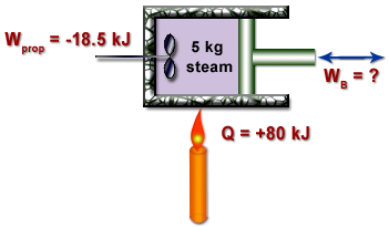
TE 303 - HW #4, P7 - 1st Law Analysis of Steam in a Closed System - 8 pts
As shown in the figure below, 5.0 kg of steam contained within a piston-and-cylinder device undergoes an expansion from state 1 where the specific internal energy is 2709.9 kJ/kg to state 2 where the specific internal energy is 2659.6 kJ/kg. During the process, there is heat transefer to the steam with a magnitude of 80 kJ. Also, a paddle wheel transfers energy to the steam by work in the amount of 18.5 kJ. There is no significant change in the kinetic or gravitational potential energies of the steam. Determine the work done by the steam on the piston during the process in kJ.

TE 303 - HW #4, P8 - Work for a "Non-Standard" P-V Relationship - 9 pts
Oxygen (O2) gas within a piston-cylinder assembly undergoes an expansion from a volume V1 = 0.01 m3 to a volume V2 = 0.03 m3. The relationship between pressure and volume during the process is P = AV-1 + B, where A = 0.06 bar m3, and B = 3.0 bar. For the O2 , determine the following:
a.) The initial and final pressures, each in bar.
b.) The work, in kJ.
a.) The initial and final pressures, each in bar.
b.) The work, in kJ.
Wednesday, September 17, 2008
TE 303 - HW #3, P1 - Steam NIST / TFT Fundamentals - 8 pts
Complete the following table for water (revisited from HW2) using either the NIST Webbook or the Thermal Fluids Excel Plug in. Be sure to cite which one that you used. Your grade will be based mostly on the use of technology, not on the answers. Your solution must be different than your solution from HW2.
T(oC) P(kPa) H(kJ/kg) x(kg vap/kg) Phase Description
a.) P = 200 kPa and x = 0.7 kg vap/kg
b.) T = 140 degC and H = 1800 kJ/kg
c.) P = 950 kPa and x = 0 kg vap/kg
d.) T = 80 degC and P = 500 kPa
e.) P = 800 kPa and H = 3161.7 kJ/kg
No Old Comments.
T(oC) P(kPa) H(kJ/kg) x(kg vap/kg) Phase Description
a.) P = 200 kPa and x = 0.7 kg vap/kg
b.) T = 140 degC and H = 1800 kJ/kg
c.) P = 950 kPa and x = 0 kg vap/kg
d.) T = 80 degC and P = 500 kPa
e.) P = 800 kPa and H = 3161.7 kJ/kg
No Old Comments.
TE 303 - HW #3, P2 - R-134a NIST/TFT Fundamentals - 12 pts
Complete the following table for R-134a(revisited from HW2) using either the NIST Webbook or the Thermal Fluids Excel Plug in. Be sure to cite which one that you used. Your grade will be based mostly on the use of technology, not on the answers. Your solution must be different than your solution from HW2.
Include an analysis of a comparison of this solution (including Problem 1) to using traditional data tables in HW2. Are the values comparable? Is interpolation still necessary? Which method is more efficient? Explain. (4 pts)
T(oF) P(psia) U(Btu/lbm) x(lbm vap/lbm) Phase Description
a.) P = 80 psia and U = 126 Btu/lbm
b.) T = 15 degF and x = 0.6 lbm vap/lbm
c.) T = 10 degF and P = 70 psia
d.) P = 180 psia and U = 226 Btu/lbm
e.) T = 110 degF and x = 1.0 lbm vap/lbm
3 Old Comments
TE 303 - HW #3, P3 - Determining DH Using Heat Capacity Polynomials - 16 pts
Determine the change in the specific enthalpy of nitrogen (N2), in kJ/kg, as it is heated from 600 to 1500 K, using:
a.) The empirical specific heat equation (Shomate Eqn) from the NIST Website.
b.) "The CoP value at the average temperature. (Use the heat capacity polynomial to determine this CoP value.)
c.) The CoP value at room temperature, 25oC. (Use the heat capacity polynomial to determine this CoP value.)
In your analysis, be sure to include a comparison of these three methods. (4 pts)
HINT: You can get the parameters for the Shomate Equation from the NIST Webbook by searching by "name", then click on "gas phase data", then "gas phase thermochemistry data". Part (a) Integral of CoP with respect to T...just like in class. Parts (b) and (c) are easier. Just evaluate CoP at ONE T and then assume CoP has this value and it is constant.
8 Old Comments
TE 303 - HW #3, P4 - Determining DU Using Heat Capacity Polynomials - 16 pts
Determine the change in the specific internal energy of hydrogen (H2), in kJ/kg, as it is heated from 400 to 1000 K, using:
a.) The empirical specific heat equation (Shomate Eqn) from the NIST Website.
b.) The CoV value at the average temperature. (Use the heat capacity polynomial to determine this CoV value.)
c.) The CoV value at room temperature, 25oC. (Use the heat capacity polynomial to determine this CoV value.)
In your analysis, be sure to include a comparison of these three methods. (4 pts)
HINT: To start this problem, copy your spreadsheet from #3 after you solved it, and then modify it for this problem. Some of the calculations are the same! Part (a) Integral of CoV with respect to T...just like in class. Parts (b) and (c) are easier. Just evaluate CoV at ONE T and then assume CoV has this value and it is constant. Remember that you are using the IDEAL GAS heat capacity.
3 Old Comments
TE 303 - HW #3, P5 - Clapeyron & Clausius-Clapeyron Equations - 16 pts
Estimate the latent heat of vaporization, in Btu/lbm, of ammonia at -10oF using:
a.) The Clapeyron equation
b.) The Clausius-Clapeyron equation
c.) The ammonia tables
In your analysis, be sure to include a comparison of these three methods and propose a reason for any significant differences. (4 pts)
13 Old Comments
a.) The Clapeyron equation
b.) The Clausius-Clapeyron equation
c.) The ammonia tables
In your analysis, be sure to include a comparison of these three methods and propose a reason for any significant differences. (4 pts)
13 Old Comments
TE 303 - HW #3, P6 - Hypothetical Process Paths and the Latent Heat of Vaporization - 24 pts

Determine the change in enthalpy in Joules for 20.0 g of heptane (C7H16) as it changes from a saturated liquid at 300 K [State 1] to a temperature of 370 K and a pressure of 58.7 kPa [State 4]; you can follow the hypothetical process path in the diagram to the right. Do not use tables of thermodynamic properties, except to check your answers. (In other words, you will not get credit for the problem if you use the tables.)
First, draw the states on a P-V or T-V diagram (4 pts). Then, calculate the DH for each step in the path using what you know about the enthalpy for each step. You might want to use the Antoine Equation to estimate the heat of vaporization of heptane at 300 K. Use the average heat capacity of heptane gas over the temperature range of interest (is this assumption valid?).
Assume heptane gas is an ideal gas at the relevant temperatures and pressures.
For the analysis section, be sure to discuss how this result differs than what you would have done using just the thermodynamics data tables, as well as the validity of your assumptions (5 pts).
HINTS: The key to the first step in this HPP is the Clausius-Clapeyron Equation. Use the Antoine equation to help you estimate the latent heat of vaporization at T1. In the second step, interpolate on the Cp data from the NIST WebBook to determine Cp(T1) and Cp(T2). Then, use the average of these two Cp's to evaluate the change in enthalpy. All you need to do is think a little bit and you will see how to evaluate ΔU34.
6 Old Comments
Wednesday, September 10, 2008
TE 303 - HW #2, P1 - Steam Table Fundamentals - 8 pts
Complete the following table for water. Be sure to cite which source of thermodynamic data tables that you used.
T(oC) P(kPa) H(kJ/kg) x(kg vap/kg) Phase Description
a.) P = 200 kPa and x = 0.7 kg vap/kg
b.) T = 140 degC and H = 1800 kJ/kg
c.) P = 950 kPa and x = 0 kg vap/kg
d.) T = 80 degC and P = 500 kPa
e.) P = 800 kPa and H = 3161.7 kJ/kg
OLD comments
T(oC) P(kPa) H(kJ/kg) x(kg vap/kg) Phase Description
a.) P = 200 kPa and x = 0.7 kg vap/kg
b.) T = 140 degC and H = 1800 kJ/kg
c.) P = 950 kPa and x = 0 kg vap/kg
d.) T = 80 degC and P = 500 kPa
e.) P = 800 kPa and H = 3161.7 kJ/kg
OLD comments
TE 303 - HW #2, P2 - R-134a Table Fundamentals - 8 pts
Complete the following table for R-134a. Be sure to cite which source of thermodynamic data tables that you used.
T(oF) P(psia) U(Btu/lbm) x(lbm vap/lbm) Phase Description
a.) P = 80 psia and U = 126 Btu/lbm
b.) T = 15 degF and x = 0.6 lbm vap/lbm
c.) T = 10 degF and P = 70 psia
d.) P = 180 psia and U = 226 Btu/lbm
e.) T = 110 degF and x = 1.0 lbm vap/lbm
OLD comments
T(oF) P(psia) U(Btu/lbm) x(lbm vap/lbm) Phase Description
a.) P = 80 psia and U = 126 Btu/lbm
b.) T = 15 degF and x = 0.6 lbm vap/lbm
c.) T = 10 degF and P = 70 psia
d.) P = 180 psia and U = 226 Btu/lbm
e.) T = 110 degF and x = 1.0 lbm vap/lbm
OLD comments
TE 303 - HW #2, P3 - R-134a Table Fundamentals - 9 pts
A 0.5 m3 vessel contains 10 kg of R-134a at -20oC. Determine…
a.) The pressure in kPa
b.) The total internal energy in kJ
c.) The volume occupied by the liquid phase in m3
OLD comments
a.) The pressure in kPa
b.) The total internal energy in kJ
c.) The volume occupied by the liquid phase in m3
OLD comments
TE 303 - HW #2, P4 - Isochoric Heating of Water - 8 pts
Five kilograms of H2O are contained in a closed, rigid tank at an initial pressure of 20 bar and a quality of 50%. Heat transfer occurs until the tank contains only saturated vapor. Determine the volume of the tank, in m3, and the final pressure in bar.
OLD comments
OLD comments
TE 303 - HW #2, P5 - Isobaric Expansion of Water - 12 pts
A piston-and-cylinder device initially contains 50 L of liquid water at 25oC and 300 kPa. Heat is added to the water at constant pressure until the entire liquid is vaporized.
a.) What is the mass of the water in the cylinder in kg ?
b.) What is the final temperature of the water in the cylinder in oC ?
c.) Determine the total enthalpy change of the water for this process, in kJ.
d.) Show the process on a completely labeled TV Diagram.
OLD comments
a.) What is the mass of the water in the cylinder in kg ?
b.) What is the final temperature of the water in the cylinder in oC ?
c.) Determine the total enthalpy change of the water for this process, in kJ.
d.) Show the process on a completely labeled TV Diagram.
OLD comments
TE 303 - HW #2, P6 - Inflating an Automobile Tire - 12 pts
The air in an automobile tire with a volume of 0.53 ft3 is at 90oF and 20 psig. Determine the mass of air that must be added to raise the pressure to the recommended value of 30 psig. Assume atmospheric pressure is 14.7 psia and both the temperature and the volume of the air in the tire remain constant as it is inflated. Assume that the air in the tire behaves as an ideal gas, but then check the validity of this assumption.
OLD comments
OLD comments
TE 303 - HW #2, P7 - An Application of Equations of State - 25 pts
A 0.016773 m3 tank contains 1 kg of R-134a at 110oC. Determine the pressure of the refrigerant using:
a.) The Ideal Gas EOS
b.) The Compressibility Factor EOS
c.) The R-134a Tables
d.) The van der Waal EOS
e.) The Soave-Redlich-Kwong EOS
In your analysis, be sure to discuss a comparison of these equations of states (5 points).
OLD comments
a.) The Ideal Gas EOS
b.) The Compressibility Factor EOS
c.) The R-134a Tables
d.) The van der Waal EOS
e.) The Soave-Redlich-Kwong EOS
In your analysis, be sure to discuss a comparison of these equations of states (5 points).
OLD comments
TE 303 - HW #2, P8 - Relative Humidity and Fogged Glasses - 8 pts
The Campus Police heard that you were a thermodynamics guru, so they have come to you to help figure out if a witness to a crime is credible. The eyewitness claims that upon entering her apartment complex, she saw the suspect leaving the downstairs apartment with some electronics equipment. Since the eyewitness must wear glasses and stated that she was wearing them at the time, the Campus Police want to know if her glasses would have fogged up when entering the building and thus obstructed her view. The temperature of the apartment complex was measured to be 20 °C, and the outdoor temperature to be 10oC. A humidity gauge indicated that the relative humidity in the apartment complex is 55%. Assuming that the eyewitness did not have anti-fog lenses, do you think that this eyewitness could have been obstructed by fogged lenses? Provide supporting calculations.
OLD comments
OLD comments
Thursday, August 21, 2008
TE 303 - Welcome to the LearnThermo Blog
For each homework problem that Dr. Pasquinelli assigns, I will post the problem statement on this blog. If you have any questions about the problem, click on the small red "comments" at the end of the problem statement. This will take you to a page where you can see all of the questions that you classmates asked, as well as my answers. If nothing you find on this page answers your question, then you can type in a new question for me. You should probably choose the "Name/URL" option for your identity. This will let you make up any name you like. This helps me state which question I am answering. But you don't need to use your real name. That way you and I can interact and no one will know who you are.
I will check this blog twice per day during the week, but you cannot rely on me on the weekend. I will probably only check the blog on Sunday night.
BUT I encourage you to answer each others questions ! You don't really, really (Shrek) understand something until you can explain it to someone else. So, try to help someone. It is anonymous. You might get a deeper understanding of the problem, and helping someone learn is a good thing to do.
I have blogged (with my students) many of the problems Dr. Pasquinelli will use in this course. You can search this blog to see the questions and answers that are already posted. I suggest you focus your search on March through June 2007.
You might also consider the supplemental example problems for Thermo-CD. These are posted on my LearnThermo webiste. Here is the link that goes directly to the additional example problems:
LearnThermo.com Examples
I look forward to working with you.
Adios,
Dr. B
TE 303 - HW #1, P1 - Mass, Force, Density and Acceleration - 10 pts
A closed system consists of 0.5 lbmole of liquid water and occupies a volume of 0.145 ft3. Determine the weight of the system, in lbf, and the average density, in lbm/ft3, at a location where the acceleration of gravity is g = 30.5 ft/s2.
TE 303 - HW #1, P2 - Mass, Weight and Acceleration - 6 pts
The weight of an object on an orbiting space station is measured to be 42 N based on an artificial acceleration of 6 m/s2. What is the weight o f the object, in N, on Earth, where g = 9.81 m/s2 ?
TE 303 - HW #1, P3 - NOx Emissions: UNITS - 6 pts
A typical car driven 12,000 miles/year emits to the atmosphere about 11 kg/year of NOx (nitrogen oxides), which causes smog in cities. Natural gas burned in a home furnace emits about 4.3 g of NOx per therm and electric power plants emit about 7.1 g NOx per kWh of electricity produced. Consider a household that has two cars and consumes 9,000 kWh of electricity and 1,200 therms of natural gas. Determine the amount of NOx emission to the atmosphere per year for which the household is responsible.
TE 303 - HW #1, P4 - Temperature Conversions: Celsius to Fahrenheit - 12 pts
Convert the following temperatures from oC to oF.
a.) 21 oC
b.) -17.78 oC
c.) -50 oC
d.) 300 oC
e.) 100 oC
f.) -273.15 oC
a.) 21 oC
b.) -17.78 oC
c.) -50 oC
d.) 300 oC
e.) 100 oC
f.) -273.15 oC
TE 303 - HW #1, P5 - Temperature Conversions: Fahrenheit to Celsius - 12 pts
Convert the following temperatures from oF to oC.
a.) 212 oF
b.) 68 oF
c.) 32 oF
d.) 0 oF
e.) -40 oF
f.) -459.67 oF
a.) 212 oF
b.) 68 oF
c.) 32 oF
d.) 0 oF
e.) -40 oF
f.) -459.67 oF
TE 303 - HW #1, P6 - Temperature Change - 6 pts
The temperature of a system rises by 72oC during a heating process. Express this temperature increase in Kelvins and degrees Rankine.
TE 303 - HW #1, P7 - Absolute and gauge Pressures - 15 pts

Tank A lies inside of Tank B, as shown in the figure. Pressure gauge A is located inside Tank B and reads 1.4 bar. Both tanks contain air. The manometer connected to Tank B contains mercury (r = 13.59 g/cm3). The manometer reading is h = 20 cm, atmospheric pressure is 101 kPa and g = 9.81 m/s2. Determine the absolute pressures inside Tank A and Tank B in kPa.
TE 303 - HW#1, P8 - Differential, Multi-Fluid Manometer - 18 pts

Fresh water and seawater flowing in parallel, horizontal pipelines are connected to each other by a double u-tube manometer, as shown in the figure. Determine the pressure difference between the two pipelines in kPa. Assume the density of seawater to be 1035 kg/m3. Can the air column be ignored in this analysis ?
Friday, June 01, 2007
Final Exam 2007
Please post any questions you have here. I will be responsive on Sunday, but not much on Saturday.
It has been a pleasure working with all of you. I hope you do well on the final. Remember you can use 3 8.5" x 11" cheat sheets (with writing on both sides) during the final.
We will take the class photo before the final on Monday morning. Sorry I forgot about it today. It is optional, you can choose not to be in the photo if you wish.
Best of luck in your career and in life.
Adios,
Dr. B
Tuesday, May 22, 2007
HW #9, P1 - Brayton Cycle with Variable Heat Capacities - 6 pts
A gas turbine power plant operates on the basic Brayton Cycle. Air is the working fluid and the cycle delivers 15 MW of power. The minimum and maximum temperatures in the cycle are 310 K and 900 K, respectively. The air pressure at the compressor outlet is 8 times the pressure at the compressor inlet. Assuming an isentropic efficiency of 80% for the compressor and 86% for the turbine, determine the mass flow rate of air through the cycle. Assume that air behaves as an ideal gas, but do not assume that the heat capacities of the air are constants.
HW #9, P2 - Brayton Cycle with Regeneration - 8 pts
A Brayton Cycle with Regeneration using air as the working fluid has a pressure ratio of 7. The minimum and maximum temperatures in the cycle are 310 K and 1150 K. Assuming an isentropic efficiency of 75% for the compressor and 82% for the turbine and an efffectiveness of 65% for the regenerator, determine...
a.) The temperature of the turbine effluent.
b.) The net work output, in kJ/kg of air flowing through the system.
c.) The thermal efficiency of the cycle.
a.) The temperature of the turbine effluent.
b.) The net work output, in kJ/kg of air flowing through the system.
c.) The thermal efficiency of the cycle.
HW #9, P3 - Effect of Turbine Feed T on Rankine Cycle Efficiency - 6 pts
Steam enters the turbine of a basic Rankine power cycle at a pressure of 10 MPa and a temperature T2, and expands adiabatically to 6 kPa. The isentropic turbine efficiency is 85%. Saturated liquid water leaves the condenser at 6 kPa and the isentropic pump efficiency is 82%.
a.) For T2 = 580oC, determine the quality of the turbine effluent and the thermal efficiency of the cycle.
b.) Plot the quality of the turbine effluent and the thermal efficiency of the cycle for values of T2 ranging from 580oC to 700oC at 10oC increments.
a.) For T2 = 580oC, determine the quality of the turbine effluent and the thermal efficiency of the cycle.
b.) Plot the quality of the turbine effluent and the thermal efficiency of the cycle for values of T2 ranging from 580oC to 700oC at 10oC increments.
HW #9, P4 - Special Rankine Cycle with Reheat and Regeneration - 8 pts
A power plant operates on a regenerative vapor power cycle with one closed feedwater heater. Steam enters the high-pressure turbine at 120 bar and 520oC and expands to 10 bar, where some of the steam is extracted and diverted to a closed feedwater heater. Condensate leaves the feedwater heater as a saturated liquid at 10 bar and then passes through an expansion valve before it is combined with the effluent from the low-pressure turbine. This combined stream flows to the condenser. The boiler feed leaves the feedwater heater at 120 bar and 170oC. The condenser pressure is 0.06 bar. Each turbine stage has an isentropic efficiency of 82%. The pump is essentially isentropic.

Determine...
a.) The thermal efficiency of the cycle.
b.) The mass flow rate of water/steam through the boiler in kg/h. if the net power output of the cycle is 320 MW.
Determine...
a.) The thermal efficiency of the cycle.
b.) The mass flow rate of water/steam through the boiler in kg/h. if the net power output of the cycle is 320 MW.
HW #9, P5 - Helium Gas Refrigeration Cycle - 6 pts
A gas refrigeration cycle with a pressure ratio of 3 uses helium as the working fluid. The temperature of the helium is -10oC at the compressor inlet and 50oC at the turbine inlet. Assuming adiabatic efficiencies of 82% for both the turbine and the compressor, determine...
a.) The minimum temperature in the cycle.
b.) The coefficient of performance.
c.) The mass flow rate of the helium in kg/s for a refrigeration load of 12 kW.
a.) The minimum temperature in the cycle.
b.) The coefficient of performance.
c.) The mass flow rate of the helium in kg/s for a refrigeration load of 12 kW.
HW #9, P6 - Ammonia Cascade Refrigeration Cycle - 8 pts
The diagram shows a two-stage, vapor-compression refrigeration system that uses ammonia as the working fluid. The system uses a flash drum to achieve intercooling. The evaporator has a refrigeration capacity of 30 tons and produces a saturated vapor effluent at -20oF. In the first compressor stage, the refrigerant is compressed adiabatically to 80 psia, which is the pressure in the mixer. Saturated vapor at 80 psia enters the second compressor stage and is compressed adiabatically to 250 psia. Each compressor stage has an isentropic efficiency of 85%. Ther are no significant pressure drops as the refrigerant passes through the heat exchangers. Saturated liquid enters each expansion valve.
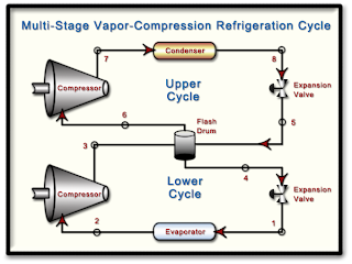
Determine...
a.) The mass flow rate of R-134a through each compressor in lbm/h.
b.) The power input to each compressor in Btu/h.
c.) The coefficient of performance of the cycle.

Determine...
a.) The mass flow rate of R-134a through each compressor in lbm/h.
b.) The power input to each compressor in Btu/h.
c.) The coefficient of performance of the cycle.
HW #9, P7 - Vapor-Compression Heat Pump - 6 pts
A vapor-compression heat pump uses R-134a as the working fluid. The refrigerant enters the compressor at 2.4 bar and 0oC at a volumetric flow rate of 0.60 m3/min. Compression is adiabatic to 9 bar and 60oC and saturated liquid leaves the condenser at 9 bar. Determine...
a.) The power input to the compressor in kW.
b.) The heating capacity of the heat pump in kW.
c.) The coefficient of performance.
d.) The isentropic compressor efficiency.
a.) The power input to the compressor in kW.
b.) The heating capacity of the heat pump in kW.
c.) The coefficient of performance.
d.) The isentropic compressor efficiency.
Monday, May 21, 2007
Monday, May 14, 2007
HW #8, P1 - Back-Work Ratio of a Steam Power Cycle - 4 pts
Consider a steam power plant that operates between the pressure limits of 10 MPa and 20 kPa. Steam enters the pump as a saturated liquid and leaves the turbine as a saturated vapor. Determine the back work ratio (BWR is the ratio of the work delivered by the turbine to the work consumed by the pump). Assume the entire cycle to be reversible and the heat losses from the pump and the turbine to be negligible.
HW #8, P2 - Isentropic Efficiency of a CO2 Compressor - 4 pts
Carbon dioxide enters an adiabatic compressor at 100 kPa and 300 K at a rate of 2.2 kg/s and exits at 600 kP and 450 K. Neglecting changes in kinetic and potential energies, determine the isentropic efficiency of the compressor.
HW #8, P3 - Analysis of an R-134a Compressor - 5 pts
R-134a enters an adiabatic compressor as saturated vapor at 120 kPa at a rate of 0.30 m3/min and exits at 1.0 MPa. If the isentropic efficiency of the compresor is 80%, determine…
a.) The temperature of the R-134a at the outlet of the compressor.
b.) The power input to the compressor in kW.
c.) Show the process path on a TS Diagram that includes the two phase envelope and all relevant isobars.
a.) The temperature of the R-134a at the outlet of the compressor.
b.) The power input to the compressor in kW.
c.) Show the process path on a TS Diagram that includes the two phase envelope and all relevant isobars.
HW #8, P4 - Polytropic Compression of N2 with Varying delta - 6 pts
Nitrogen gas is compressed from 80 kPa and 27oC to 480 kPa by a 10 kW compressor. Determine the mass flow rate of nitrogen through the compressor assuming the compression process is …
a.) Isentropic, gamma = 1.4
b.) Polytropic with delta = 1.3
c.) Isothermal
d.) Ideal, two-stage polytropic with delta = 1.3
a.) Isentropic, gamma = 1.4
b.) Polytropic with delta = 1.3
c.) Isothermal
d.) Ideal, two-stage polytropic with delta = 1.3
HW #8, P5 - Lost Work in a Heat Exchanger - 4 pts
A well-insulated shell-and-tube heat exchanger is used to heat water (CP = 4.18 kJ/kg-K) in the tubes from 20oC to 70oC at a rate of 4.5 kg/s. Heat is supplied by hot oil (CP = 2.30 kJ/kg-K) that enters the shell side at 170oC at a rate of 10 kg/s. Disregarding any heat loss from the heat exchanger, determine...

a.) The exit temperature of the oil.
b.) The rate of entropy generation in the heat exchanger.
c.) The rate at which work is lost due to the irreversible nature of heat transfer in this process in kW. Assume the surroundings are at 20oC.

a.) The exit temperature of the oil.
b.) The rate of entropy generation in the heat exchanger.
c.) The rate at which work is lost due to the irreversible nature of heat transfer in this process in kW. Assume the surroundings are at 20oC.
HW #8, P6 - Entropy Change, Heat Transfer and Irreversibilities - 3 pts
A closed system undergoes a process in which work is done on the system and heat transfer Q occurs only at temperature Tb. For each case listed below, determine whether the entropy change of the system is positive, negative, zero or indeterminate (you cannot tell for sure from the given information).
a.) Internally reversible process with Q > 0.
b.) Internally reversible process with Q = 0.
c.) Internally reversible process with Q < 0.
d.) Internal irreversibilities present with Q > 0.
e.) Internal irreversibilities present with Q = 0.
f.) Internal irreversibilities present with Q < 0.
a.) Internally reversible process with Q > 0.
b.) Internally reversible process with Q = 0.
c.) Internally reversible process with Q < 0.
d.) Internal irreversibilities present with Q > 0.
e.) Internal irreversibilities present with Q = 0.
f.) Internal irreversibilities present with Q < 0.
HW #8, P7 - Entropy Generation and Lost Work in a Nozzle - 5 pts
Oxygen, O2, enters a nozzle operating at steady-state at 3.8 MPa, 387oC and 10 m/s. At the nozzle exit, the conditions are 150 kPa, 37oC and 790 m/s.
a.) For a system that encloses the nozzle only, determine the heat transfer (kJ/kg) and the change in specific entropy (kJ/kg-K), both per kg of oxygen flowing through the nozzle. What additional information would be required to evaluate the rate of entropy production in this process ?
b.) Using an enlarged system boundary that includes the nozzle and a portion of its immediate surroundings, evaluate the rate of entropy generation (kJ/kg-K) and the rate of lost work (kJ/kg), both per kg of oxygen flowing through the nozzle. Assume that heat exchange at the enlarged system boundary takes place at the ambient temperature, 20oC.
Treat O2 as an ideal gas with variable heat capacities. Verify that the ideal gas assumption is valid.
HW #8, P8 - Lost Work in an Air Compressor and HEX - 6 pts
Air flows through the compressor and heat exchanger in the system shown in the diagram. A separate liquid water stream (CP,W = 4.18 kJ/kg-K) also flows through the heat exchanger. The data given on the diagram are based on steady-state operation. Consider the air to be an ideal gas and neglect heat exchange with the surroundings as well as changes in kinetic and potential energies. Determine...

a.) The compressor power requirement in kW and the mass flow rate of the cooling water in kg/s.
b.) The rate of entropy generation in kW/K and the rate at which work is lost in kW for the compressor. Assume the temperature of the surroundings is 300 K.
c.) The rate of entropy generation in kW/K and the rate at which work is lost in kW for the heat exchanger. Assume the temperature of the surroundings is 300 K.
Wednesday, April 25, 2007
HW #7, P1 - The Increase of Entropy Principle - 3 pts
a.) Will the entropy of steam increase, decrease or remain the same as it flows through a real adiabatic turbine ?
b.) Will the entropy of the working fluid in an ideal Carnot Cycle increase, decrease or remain the same during the isothermal heat addition process ?
c.) Steam is accelerated as it flows through a real, adiabatic nozzle. Will the entropy of the steam at the nozzle exit be greater than, equal to or less than the entropy at the nozzle inlet ?
HW #7, P2 - Efficiency of an Int. Rev. HE with Multiple Heat Transfers - 4 pts
A system executes a power cycle while receiving 750 kJ by heat transfer at 1500 K and rejecting 100 kJ of heat at 500 K. A heat transfer from the system also occurs at 1000 K. There are no other heat transfers. If no internal irreversibilities exist in this system, determine the thermal efficiency of this cycle.
HW #7, P3 - Efficiency and Tres for Rev. and Irrev. Cycles - 6 pts
Complete the following involving reversible and irreversible cycles.
a.) Reversible and irreversible power cycles each discharge QC to a cold reservoir at TC and receive energy QH from hot reservoirs at TH and T'H, respectively. There are no other heat transfers involved. Show that T'H> TH.
b.) Reversible and irreversible refrigeration cycles each discharge QH to a hot reservoir at TH and receive energy QC from cold reservoirs at TC and T'C, respectively. There are no other heat transfers involved. Show that T'C> TC.
Subscribe to:
Posts (Atom)