Please post any questions you have here. I will be responsive on Sunday, but not much on Saturday.
It has been a pleasure working with all of you. I hope you do well on the final. Remember you can use 3 8.5" x 11" cheat sheets (with writing on both sides) during the final.
We will take the class photo before the final on Monday morning. Sorry I forgot about it today. It is optional, you can choose not to be in the photo if you wish.
Best of luck in your career and in life.
Adios,
Dr. B
Friday, June 01, 2007
Tuesday, May 22, 2007
HW #9, P1 - Brayton Cycle with Variable Heat Capacities - 6 pts
A gas turbine power plant operates on the basic Brayton Cycle. Air is the working fluid and the cycle delivers 15 MW of power. The minimum and maximum temperatures in the cycle are 310 K and 900 K, respectively. The air pressure at the compressor outlet is 8 times the pressure at the compressor inlet. Assuming an isentropic efficiency of 80% for the compressor and 86% for the turbine, determine the mass flow rate of air through the cycle. Assume that air behaves as an ideal gas, but do not assume that the heat capacities of the air are constants.
HW #9, P2 - Brayton Cycle with Regeneration - 8 pts
A Brayton Cycle with Regeneration using air as the working fluid has a pressure ratio of 7. The minimum and maximum temperatures in the cycle are 310 K and 1150 K. Assuming an isentropic efficiency of 75% for the compressor and 82% for the turbine and an efffectiveness of 65% for the regenerator, determine...
a.) The temperature of the turbine effluent.
b.) The net work output, in kJ/kg of air flowing through the system.
c.) The thermal efficiency of the cycle.
a.) The temperature of the turbine effluent.
b.) The net work output, in kJ/kg of air flowing through the system.
c.) The thermal efficiency of the cycle.
HW #9, P3 - Effect of Turbine Feed T on Rankine Cycle Efficiency - 6 pts
Steam enters the turbine of a basic Rankine power cycle at a pressure of 10 MPa and a temperature T2, and expands adiabatically to 6 kPa. The isentropic turbine efficiency is 85%. Saturated liquid water leaves the condenser at 6 kPa and the isentropic pump efficiency is 82%.
a.) For T2 = 580oC, determine the quality of the turbine effluent and the thermal efficiency of the cycle.
b.) Plot the quality of the turbine effluent and the thermal efficiency of the cycle for values of T2 ranging from 580oC to 700oC at 10oC increments.
a.) For T2 = 580oC, determine the quality of the turbine effluent and the thermal efficiency of the cycle.
b.) Plot the quality of the turbine effluent and the thermal efficiency of the cycle for values of T2 ranging from 580oC to 700oC at 10oC increments.
HW #9, P4 - Special Rankine Cycle with Reheat and Regeneration - 8 pts
A power plant operates on a regenerative vapor power cycle with one closed feedwater heater. Steam enters the high-pressure turbine at 120 bar and 520oC and expands to 10 bar, where some of the steam is extracted and diverted to a closed feedwater heater. Condensate leaves the feedwater heater as a saturated liquid at 10 bar and then passes through an expansion valve before it is combined with the effluent from the low-pressure turbine. This combined stream flows to the condenser. The boiler feed leaves the feedwater heater at 120 bar and 170oC. The condenser pressure is 0.06 bar. Each turbine stage has an isentropic efficiency of 82%. The pump is essentially isentropic.

Determine...
a.) The thermal efficiency of the cycle.
b.) The mass flow rate of water/steam through the boiler in kg/h. if the net power output of the cycle is 320 MW.
Determine...
a.) The thermal efficiency of the cycle.
b.) The mass flow rate of water/steam through the boiler in kg/h. if the net power output of the cycle is 320 MW.
HW #9, P5 - Helium Gas Refrigeration Cycle - 6 pts
A gas refrigeration cycle with a pressure ratio of 3 uses helium as the working fluid. The temperature of the helium is -10oC at the compressor inlet and 50oC at the turbine inlet. Assuming adiabatic efficiencies of 82% for both the turbine and the compressor, determine...
a.) The minimum temperature in the cycle.
b.) The coefficient of performance.
c.) The mass flow rate of the helium in kg/s for a refrigeration load of 12 kW.
a.) The minimum temperature in the cycle.
b.) The coefficient of performance.
c.) The mass flow rate of the helium in kg/s for a refrigeration load of 12 kW.
HW #9, P6 - Ammonia Cascade Refrigeration Cycle - 8 pts
The diagram shows a two-stage, vapor-compression refrigeration system that uses ammonia as the working fluid. The system uses a flash drum to achieve intercooling. The evaporator has a refrigeration capacity of 30 tons and produces a saturated vapor effluent at -20oF. In the first compressor stage, the refrigerant is compressed adiabatically to 80 psia, which is the pressure in the mixer. Saturated vapor at 80 psia enters the second compressor stage and is compressed adiabatically to 250 psia. Each compressor stage has an isentropic efficiency of 85%. Ther are no significant pressure drops as the refrigerant passes through the heat exchangers. Saturated liquid enters each expansion valve.
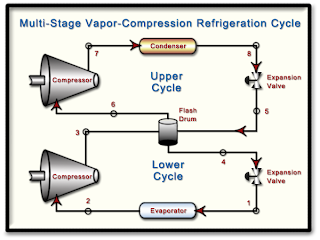
Determine...
a.) The mass flow rate of R-134a through each compressor in lbm/h.
b.) The power input to each compressor in Btu/h.
c.) The coefficient of performance of the cycle.

Determine...
a.) The mass flow rate of R-134a through each compressor in lbm/h.
b.) The power input to each compressor in Btu/h.
c.) The coefficient of performance of the cycle.
HW #9, P7 - Vapor-Compression Heat Pump - 6 pts
A vapor-compression heat pump uses R-134a as the working fluid. The refrigerant enters the compressor at 2.4 bar and 0oC at a volumetric flow rate of 0.60 m3/min. Compression is adiabatic to 9 bar and 60oC and saturated liquid leaves the condenser at 9 bar. Determine...
a.) The power input to the compressor in kW.
b.) The heating capacity of the heat pump in kW.
c.) The coefficient of performance.
d.) The isentropic compressor efficiency.
a.) The power input to the compressor in kW.
b.) The heating capacity of the heat pump in kW.
c.) The coefficient of performance.
d.) The isentropic compressor efficiency.
Monday, May 21, 2007
Monday, May 14, 2007
HW #8, P1 - Back-Work Ratio of a Steam Power Cycle - 4 pts
Consider a steam power plant that operates between the pressure limits of 10 MPa and 20 kPa. Steam enters the pump as a saturated liquid and leaves the turbine as a saturated vapor. Determine the back work ratio (BWR is the ratio of the work delivered by the turbine to the work consumed by the pump). Assume the entire cycle to be reversible and the heat losses from the pump and the turbine to be negligible.
HW #8, P2 - Isentropic Efficiency of a CO2 Compressor - 4 pts
Carbon dioxide enters an adiabatic compressor at 100 kPa and 300 K at a rate of 2.2 kg/s and exits at 600 kP and 450 K. Neglecting changes in kinetic and potential energies, determine the isentropic efficiency of the compressor.
HW #8, P3 - Analysis of an R-134a Compressor - 5 pts
R-134a enters an adiabatic compressor as saturated vapor at 120 kPa at a rate of 0.30 m3/min and exits at 1.0 MPa. If the isentropic efficiency of the compresor is 80%, determine…
a.) The temperature of the R-134a at the outlet of the compressor.
b.) The power input to the compressor in kW.
c.) Show the process path on a TS Diagram that includes the two phase envelope and all relevant isobars.
a.) The temperature of the R-134a at the outlet of the compressor.
b.) The power input to the compressor in kW.
c.) Show the process path on a TS Diagram that includes the two phase envelope and all relevant isobars.
HW #8, P4 - Polytropic Compression of N2 with Varying delta - 6 pts
Nitrogen gas is compressed from 80 kPa and 27oC to 480 kPa by a 10 kW compressor. Determine the mass flow rate of nitrogen through the compressor assuming the compression process is …
a.) Isentropic, gamma = 1.4
b.) Polytropic with delta = 1.3
c.) Isothermal
d.) Ideal, two-stage polytropic with delta = 1.3
a.) Isentropic, gamma = 1.4
b.) Polytropic with delta = 1.3
c.) Isothermal
d.) Ideal, two-stage polytropic with delta = 1.3
HW #8, P5 - Lost Work in a Heat Exchanger - 4 pts
A well-insulated shell-and-tube heat exchanger is used to heat water (CP = 4.18 kJ/kg-K) in the tubes from 20oC to 70oC at a rate of 4.5 kg/s. Heat is supplied by hot oil (CP = 2.30 kJ/kg-K) that enters the shell side at 170oC at a rate of 10 kg/s. Disregarding any heat loss from the heat exchanger, determine...

a.) The exit temperature of the oil.
b.) The rate of entropy generation in the heat exchanger.
c.) The rate at which work is lost due to the irreversible nature of heat transfer in this process in kW. Assume the surroundings are at 20oC.

a.) The exit temperature of the oil.
b.) The rate of entropy generation in the heat exchanger.
c.) The rate at which work is lost due to the irreversible nature of heat transfer in this process in kW. Assume the surroundings are at 20oC.
HW #8, P6 - Entropy Change, Heat Transfer and Irreversibilities - 3 pts
A closed system undergoes a process in which work is done on the system and heat transfer Q occurs only at temperature Tb. For each case listed below, determine whether the entropy change of the system is positive, negative, zero or indeterminate (you cannot tell for sure from the given information).
a.) Internally reversible process with Q > 0.
b.) Internally reversible process with Q = 0.
c.) Internally reversible process with Q < 0.
d.) Internal irreversibilities present with Q > 0.
e.) Internal irreversibilities present with Q = 0.
f.) Internal irreversibilities present with Q < 0.
a.) Internally reversible process with Q > 0.
b.) Internally reversible process with Q = 0.
c.) Internally reversible process with Q < 0.
d.) Internal irreversibilities present with Q > 0.
e.) Internal irreversibilities present with Q = 0.
f.) Internal irreversibilities present with Q < 0.
HW #8, P7 - Entropy Generation and Lost Work in a Nozzle - 5 pts
Oxygen, O2, enters a nozzle operating at steady-state at 3.8 MPa, 387oC and 10 m/s. At the nozzle exit, the conditions are 150 kPa, 37oC and 790 m/s.
a.) For a system that encloses the nozzle only, determine the heat transfer (kJ/kg) and the change in specific entropy (kJ/kg-K), both per kg of oxygen flowing through the nozzle. What additional information would be required to evaluate the rate of entropy production in this process ?
b.) Using an enlarged system boundary that includes the nozzle and a portion of its immediate surroundings, evaluate the rate of entropy generation (kJ/kg-K) and the rate of lost work (kJ/kg), both per kg of oxygen flowing through the nozzle. Assume that heat exchange at the enlarged system boundary takes place at the ambient temperature, 20oC.
Treat O2 as an ideal gas with variable heat capacities. Verify that the ideal gas assumption is valid.
HW #8, P8 - Lost Work in an Air Compressor and HEX - 6 pts
Air flows through the compressor and heat exchanger in the system shown in the diagram. A separate liquid water stream (CP,W = 4.18 kJ/kg-K) also flows through the heat exchanger. The data given on the diagram are based on steady-state operation. Consider the air to be an ideal gas and neglect heat exchange with the surroundings as well as changes in kinetic and potential energies. Determine...

a.) The compressor power requirement in kW and the mass flow rate of the cooling water in kg/s.
b.) The rate of entropy generation in kW/K and the rate at which work is lost in kW for the compressor. Assume the temperature of the surroundings is 300 K.
c.) The rate of entropy generation in kW/K and the rate at which work is lost in kW for the heat exchanger. Assume the temperature of the surroundings is 300 K.
Wednesday, April 25, 2007
HW #7, P1 - The Increase of Entropy Principle - 3 pts
a.) Will the entropy of steam increase, decrease or remain the same as it flows through a real adiabatic turbine ?
b.) Will the entropy of the working fluid in an ideal Carnot Cycle increase, decrease or remain the same during the isothermal heat addition process ?
c.) Steam is accelerated as it flows through a real, adiabatic nozzle. Will the entropy of the steam at the nozzle exit be greater than, equal to or less than the entropy at the nozzle inlet ?
HW #7, P2 - Efficiency of an Int. Rev. HE with Multiple Heat Transfers - 4 pts
A system executes a power cycle while receiving 750 kJ by heat transfer at 1500 K and rejecting 100 kJ of heat at 500 K. A heat transfer from the system also occurs at 1000 K. There are no other heat transfers. If no internal irreversibilities exist in this system, determine the thermal efficiency of this cycle.
HW #7, P3 - Efficiency and Tres for Rev. and Irrev. Cycles - 6 pts
Complete the following involving reversible and irreversible cycles.
a.) Reversible and irreversible power cycles each discharge QC to a cold reservoir at TC and receive energy QH from hot reservoirs at TH and T'H, respectively. There are no other heat transfers involved. Show that T'H> TH.
b.) Reversible and irreversible refrigeration cycles each discharge QH to a hot reservoir at TH and receive energy QC from cold reservoirs at TC and T'C, respectively. There are no other heat transfers involved. Show that T'C> TC.
HW #7, P4 - ΔSSys, ΔSRes, and ΔSUniv, for a H.T. Process - 3 pts
During the isothermal heat addition process of a Carnot Cycle, 900 kJ of heat is added to the working fluid from a source at 400oC. Determine:
a.) the entropy change of the working fluid
b.) the entropy change of the heat source
c.) the total entropy change of the universe for this process.
a.) the entropy change of the working fluid
b.) the entropy change of the heat source
c.) the total entropy change of the universe for this process.
HW #7, P5 - Specific Entropy Change Using Tabluar Data - 4 pts
Using the appropriate table, determine the change in specific entropy in kJ/kg-K for:
a.) Water: P1 = 10 MPa, T1 = 400oC and P2 = 10 MPa, T2 = 100oC.
b.) R-134a: H1 = 211.44 kJ/kg, T1 = - 40oC and P2 = 5 bar, x2 = 1.0.
c.) Air (IG): T1 = 7oC, P1 = 2 bar and T2 = 327oC, P2 = 1 bar.
d.) Hydrogen (H2, IG): T1 = 727oC, P1 = 1 bar and T2 = 25oC, P2 = 3 bar.
a.) Water: P1 = 10 MPa, T1 = 400oC and P2 = 10 MPa, T2 = 100oC.
b.) R-134a: H1 = 211.44 kJ/kg, T1 = - 40oC and P2 = 5 bar, x2 = 1.0.
c.) Air (IG): T1 = 7oC, P1 = 2 bar and T2 = 327oC, P2 = 1 bar.
d.) Hydrogen (H2, IG): T1 = 727oC, P1 = 1 bar and T2 = 25oC, P2 = 3 bar.
HW #7, P6 - "Show That" for a Cycle Interacting with Three Reservoirs - ?? pts
The system shown in the figure undergoes a cycle while receiving energy at the rate Qsurr from the surroundings at temperature Tsurr, receiving QH from a heat source at temperature TH, and rejecting QC to a thermal reservoir at TC. Derive an expression for the maximum theoretical value of QC in terms of QH and Tsurr, TH and TC only.
HW #7, P7 - Three-Step, Ideal Gas Cycle Analysis - 8 pts
A quantity of air undergoes a thermodynamic cycle consisting of three internally reversible processes in series. Assume that the air behaves as an ideal gas. This may not be a good assumption, but let's work with it here anyway.
Step 1 - 2 : Isothermal expansion at 250 K from 4.75 bar to 1.0 bar.
Step 2 - 3 : Adiabatic compression to 4.75 bar.
Step 3 - 1 : Isobaric cooling.
a.) Sketch the cycle on a PV diagram.
b.) Sketch the cycle on a TS diagram.
c.) Determine T3 in Kelvin
d.) If the cycle is a power cycle, determine its thermal efficiency. If the cycle is a refrigeration cycle, determine its COP.
HW #7, P8 - Entropy Change in the Evaporator of a Refrigerator - ?? pts
R-134a enters the coils of the evaporator of a refrigeration system as a saturated vapor-liquid mixture at a pressure of 200 kPa. The refrigerant absorbs 120 kJ of heat from the cooled space, which is maintained at -5oC, and leaves the evaporator as a saturated vapor at the same pressure. Determine...
a.) The entropy change of the refrigerant.
b.) The entropy change of the refrigerated space.
c.) The entropy change of the universe for the process.
a.) The entropy change of the refrigerant.
b.) The entropy change of the refrigerated space.
c.) The entropy change of the universe for the process.
HW #7, P9 - Maximum Work From an Adiabatic Turbine - ?? pts
Steam enters an adiabatic turbine at 800 psia and 900oF and leaves at a pressure of 40 psia. Determine the maximum amount of work that can be delivered by this turbine.
HW #7, P10 - DeltaS{Univ} Upon Quenching an Iron Block - ?? pts
A 12 kg iron block initially at 350oC is quenched in an insulated tank that contains 100 kg of water at 22oC. Assuming the water that vaporizes during the process condenses back into the liquid phase inside the tank, determine the entropy change of the universe for this process.
HW #7, P11 - DeltaS for Heat Transfer to R-134a in a Rigid Tank - ?? pts
A 0.5 m3 rigid tank contains R-134a initially at 200 kPa and 40% quality. Heat is transferred to the refrigerant from a source at 35oC until the pressure rises to 400 kPa. Determine…
a.) The entropy change of the R-134a.
b.) The entropy change of the heat source.
c.)The entropy change of the universe for this process.
a.) The entropy change of the R-134a.
b.) The entropy change of the heat source.
c.)The entropy change of the universe for this process.
Tuesday, April 24, 2007
HW #6, P1 - "Show That" Using the K-P Statement of the 2nd Law - 6 pts
Using the Kelvin-Planck statement of the 2nd Law, demonstrate the following corollaries.
a.) The coefficient of performance (COP) of an irreversible heat pump cycle is always less than the COP of a reversible heat pump when both heat pumps exchange heat with the same two thermal reservoirs.
b.) All reversible heat pump cycles exchanging heat with the same two thermal reservoirs have the same COP.
HW #6, P2 - Rev., Irrev. and Impossible Refrigeration Cycles - 8 pts
A refrigeration cycle operating between two reservoirs receives QC from a cold reservoir at TC = 250 K and rejects QH to a hot reservoir at TH = 300 K. For each of the following cases, determine whether the cycle is reversible, irreversible or impossible.
a.) QC = 1000 kJ and Wcycle = 400 kJ
b.) QC = 1500 kJ and QH = 1800 kJ
c.) QH = 1500 kJ and Wcycle = 200 kJ
d.) COP = 4
a.) QC = 1000 kJ and Wcycle = 400 kJ
b.) QC = 1500 kJ and QH = 1800 kJ
c.) QH = 1500 kJ and Wcycle = 200 kJ
d.) COP = 4
HW #6, P3 - A Reversible HE Used to Drive a Reversible Heat Pump - 6 pts
A reversible power cycle receives QH from a reservoir at TH and rejects QC to a reservoir at TC. The work developed by the power cycle is used to drive a reversible heat pump that removes Q'C from a reservoir at T'C and rejects Q'H to a reservoir at T'H.
HW #6, P4 - Effect of Source and Sink Temperatures on HE Efficiency - 6 pts
A heat engine operates between a source at TH and a sink at TC. Heat is supplied to the heat engine at a steady rate of 1200 kJ/min. Study the effects of TH and TC on the maximum power produced and the maximum cycle efficiency. For TC = 25oC, let TH vary from 300oC to 1000oC. Create plots of Wcycle and ηth as functions of TH. For TH = 550oC, let TC vary from 0oC to 50oC. Create plots of Wcycle and ηth as functions of TC. Discuss the results.
HW #6, P5 - Maximum Efficiency of a Geothermal Power Plant - 2 pts
Geothermal power plants harness underground sources of hot water or steam for the production of electricity. One such plant receives a supply of hot water at 167oC and rejects heat to the atmosphere, which is at 13oC. Determine the maximum possible thermal efficiency for any power cycle operating between these two temperatures.
HW #6, P6 - Carnot Gas Power Cycle Analysis - 8 pts
One kg of air as an ideal gas executes a Carnot power cycle having a thermal efficiency of 60%. The heat transfer to the air during the isothermal expansion is 40 kJ. At the end of the isothermal expansion, the pressure is 5.6 bar and the volume is 0.3 m3. Determine...
a.) The maximum and mininmum temperatures for the cycle in Kelvin.
b.) The pressure in bar and volume in m3 at the beginning of the isothermal expansion.
c.) The work and heat transfer for each of the four processes in kJ.
Assume: CV,air = 0.731 kJ/kg-K (constant).
d.) Sketch the cycle on a PV diagram.
HW #6, P7 - Carnot HE Used to Drive a Carnot Refrigerator - 6 pts
A Carnot Heat Engine receives heat from a reservoir at 900oC at a rate of 800 kJ/min and rejects the waste heat to the ambient air at 27oC. The entire work output of the heat engine is used to drive a refrigerator that removes heat from the refrigerated space at -5oC and rejects heat to the same ambient air at 27oC. Determine:
a.) the maximum rate of heat removal from the refrigerated space
b.) the total rate of heat rejection to the ambient air
a.) the maximum rate of heat removal from the refrigerated space
b.) the total rate of heat rejection to the ambient air
HW #6, P8 - Ammonia Carnot Vapor Refrigeration Cycle - 10 pts
Three kg of ammonia executes a Carnot vapor refrigeration cycle. During the isothermal compression (cooling) step, the ammonia begins as a saturated mixture at 10 bar with a quality of 97% and it is cooled until it is a saturated liquid. The adiabatic compression step requires 128 kJ/kg of work to increase the pressure from 1.1 bar to 10 bar.
a.) Sketch the cycle on a PV diagram.
b.) Evaluate the heat and work for each process in kJ.
c.) Evaluate the COP for this cycle.
a.) Sketch the cycle on a PV diagram.
b.) Evaluate the heat and work for each process in kJ.
c.) Evaluate the COP for this cycle.
Sunday, April 15, 2007
HW #5, P1 - Adiabatic Steam Nozzle - 5 pts
Steam at 3 MPa and 400oC enters an adiabatic nozzle at a velocity of 40 m/s and leaves at 2.5 MPa and 300 m/s. Determine…
a.) The temperature of the steam when it leaves the nozzle.
b.) The ratio of the inlet cross-sectional area to the outlet cross-sectional area, A1 / A2.
Assume the process operates at steady-state.
a.) The temperature of the steam when it leaves the nozzle.
b.) The ratio of the inlet cross-sectional area to the outlet cross-sectional area, A1 / A2.
Assume the process operates at steady-state.
HW #5, P2 - Adiabatic Gas Turbine - 5 pts
Argon gas enters an adiabatic turbine at 900 kPa and 450oC with a velocity of 80 m/s and leaves at 150 kPa and a velocity of 150 m/s. The inlet cross-sectional area is 60 cm2. If the power output of the turbine is 250 kW, determine the exit temperature of the argon. The process operates at steady-state and argon behaves as an ideal gas.
HW #5, P3 - Effluent Pressure in a Non-Adiabatic Steam Diffuser - 6 pts
Steam enters a diffuser at a pressure of 14.7 psia, a temperature of 300oF and a velocity of 500 ft/s. Steam exits the diffuser as a saturated vapor with negligible kinetic energy. Heat transfer occurs from the steam to the surroundings at a rate of 19.59 Btu/lbm of flowing steam. Neglecting potential energy effects, determine the exit pressure in psia. Assume the diffuser operates at steady-state.
HW #5, P4 - Analysis of a Two-Stage, Adiabatic Turbine - 6 pts
A well-insulated two-stage turbine operating at steady-state is shown in the diagram. Steam enters at 3 MPa and 400oC with a volumetric flow rate of 85 m3/min. Some steam is extracted from the turbine at a pressure of 0.5 MPa and a temperature of 180oC. The rest expands to a pressure of 6 kPa and a quality of 90%. The total power developed by the turbine is 11,400 kW. Changes in kinetic and potential energies are negligible. Determine:
a.) The mass flow rate of the steam at each of the two exits.
b.) The diameter in meters of the duct through which the 0.5 MPa steam is extracted if the velocity there is 20 m/s.

a.) The mass flow rate of the steam at each of the two exits.
b.) The diameter in meters of the duct through which the 0.5 MPa steam is extracted if the velocity there is 20 m/s.

HW #5, P5 - Analysis of an Adiabatic Steam De-Superheater - 6 pts
As shown in the diagram, 15 kg/s of steam enters a de-superheater operating at steady-state at 30 bar and 320oC where it is mixed with liquid water at 25 bar and temperature T3 to produce saturated vapor at 20 bar. Heat transfer between the device and its surroundings and changes in kinetic and potentail energies are negligible.
a.) If T3 = 200oC, determine the mass flow rate of stream 3.
b.) Plot the mass flow rate of stream 3 in kg/s as a function of T3 as T3 ranges from 20 to 220oC.

a.) If T3 = 200oC, determine the mass flow rate of stream 3.
b.) Plot the mass flow rate of stream 3 in kg/s as a function of T3 as T3 ranges from 20 to 220oC.

HW #5, P6 - Pump Horsepower Requirment - 6 pts
The pump shown here increases the pressure in liquid water from 200 to 4000 kPa. What is the minimum horsepower motor required to drive the pump for a flow rate of 0.1 m3 /s ?


HW #5, P7 - Waste Heat Steam Generator - 6 pts
At steady-state, water enters the waste heat recovery steam generator shown in the diagram at 42 psia and 220oF and exits at 40 psia and 320oF. The steam is then fed into a turbine from which it exits at 1 psia and a quality of 90%. Air from an oven exhaust enters the steam generator at 360oF and 1 atm with a volumetric flow rate of 3000 ft3/min and exits at 280oF and 1 atm. Ignore all heat exchange with the surroundings and any changes in potential and kinetic energies. Determine the power developed by the turbine in horsepower.
CP,air = 7.05 Btu/lbmole-oF.

CP,air = 7.05 Btu/lbmole-oF.

HW #5, P8 - Transient Heating of an Office Space - 7 pts
The air supply to a 2000 ft3 office has been shut off overnight to conserve utilities, and the room temperature has dropped to 40oF. In the morning, a worker resets the thermostat to 70oF, and 200 ft3/min of air at 120oF begins to flow into the office through a heating duct. The air is well-mixed within the room and an equal mass flow of air at room temperature is withdrawn through a return duct. The air pressure is essentially 1 atm everywhere. Ignoring heat exchange with the surroundings, as well as any changes in kinetic or potential energies, estimate how long it takes for the room temperature to reach 70oF. Plot room temperature as a function of time. Assume g = 1.4 for the air.
HINTS :
This is a transient or unsteady process because helium enters the system (the balloon). Assume the He behaves as an ideal gas, but check to see if this is a good assumption. Use the IG EOS to determine the initial mass of He in the balloon. After you determine V2, calculating Wb is easy ! Then, simultaneously solve two equations in two unknowns. The equations are: the IG EOS applied to the final state of the balloon and the transient form of the 1st Law applied to this process. The two unknowns are: T2, mHe,2 .
The catch is that we must determine values for U1, U2 and Hin. These are NOT ΔU's and ΔH's but real U's and H's. In order to do this (just like the steam tables) we MUST choose a reference state. A reference state is a T, P and phase at which YOU choose to make EITHER U or H zero kJ/kg. I want you to use a reference state of U = 0 for He gas at 22 oC and 100 kPa. The P doesn't actually matter because He is treated as an IG in this problem so U and H are not functions of P anyway.
Once you have a ref state, use a Hypothetical Process Path from the ref state to states 1, 2 and inlet to evaluate U1, U2 and Hin using the IG EOS and CV and CP given in the problem.
For He, use: CP = 5.1926 kJ/kg-K and CV = 3.1156 kJ/kg-K.
HW #5, P9 - Filling a Balloon with Helium - 10 pts
A balloon initially contains 65 m3 of helium gas at atmospheric conditions of 100 kPa and 22oC. The balloon is connected by a valve to a large reservoir that supplies helium gas at 150 kPa and 25oC. Now, the valve is opened and helium is alowed to enter the balloon until pressure equilibrium with the helium at the supply line is reached. The material of the balloon is such that its volume increases linearly with pressure. If no heat transfer takes place during this process, determine the final temperature of the helium in the balloon.
This is a transient or unsteady process because helium enters the system (the balloon). Assume the He behaves as an ideal gas, but check to see if this is a good assumption. Use the IG EOS to determine the initial mass of He in the balloon. After you determine V2, calculating Wb is easy ! Then, simultaneously solve two equations in two unknowns. The equations are: the IG EOS applied to the final state of the balloon and the transient form of the 1st Law applied to this process. The two unknowns are: T2, mHe,2 .
The catch is that we must determine values for U1, U2 and Hin. These are NOT ΔU's and ΔH's but real U's and H's. In order to do this (just like the steam tables) we MUST choose a reference state. A reference state is a T, P and phase at which YOU choose to make EITHER U or H zero kJ/kg. I want you to use a reference state of U = 0 for He gas at 22 oC and 100 kPa. The P doesn't actually matter because He is treated as an IG in this problem so U and H are not functions of P anyway.
Once you have a ref state, use a Hypothetical Process Path from the ref state to states 1, 2 and inlet to evaluate U1, U2 and Hin using the IG EOS and CV and CP given in the problem.
For He, use: CP = 5.1926 kJ/kg-K and CV = 3.1156 kJ/kg-K.
Wednesday, April 11, 2007
HW #4, P1 - Compression of Cooling Air by a Linear Spring - 6 pts
Warm air is conatined in a piston-and-cylinder device oriented horizontally, as shown below. The air cools slowly from an initial volume of 0.003 m3 to a final volume of 0.002 m3. During this process, the spring exerts a force that varies linearly from 900 N to a final value of zero N. The atmospheric pressure is 100 kPa and the area of the piston face is 0.018 m2. Friction between the piston and cylinder wall can be neglected because the process occurs so slowly. For the air, determine the initial and final pressures in kPa and the boundary work for the process in kJ.


HW #4, P2 - Work and Heat Transfer for a Closed, 3-Step Cycle - 6 pts
A closed system undergoes a thermodynamic cycle consisting of the following processes:
Process 1 - 2: Adiabatic compression from P1 = 50 psia, V1 = 3.0 ft3 to V2 = 1 ft3 along a path described by :

Process 2 - 3: Constant volume.
Process 3 - 1: Constant pressure with U1 - U3 = 46.7 Btu.
There are no significant changes in kinetic or potential energies in any of these processes.
a.) Sketch this cycle on a PV Diagram.
b.) Calculate the net work for the cycle in Btu.
c.) Calculate the heat transfer for process 2-3.
HW #4, P3 - Heat Conduction Through a Composite Wall - 4 pts
A composite plane wall consists of a 9 inch thick layer of brick and a 4 inch thick layer of insulation. The outer surface temperatures of the brick and insulation are 1260oR and 560oR, respectively, and there is perfect contact at the interface between the brick and the insulation. At steady-state, determine the heat conduction flux through the wall in Btu/h-ft2 and the temperature in oR at the interface between the brick and the insulation.
Brick Insulation
Data : k 1.4 0.05 Btu/h-ft2-oR
Brick Insulation
Data : k 1.4 0.05 Btu/h-ft2-oR
HW #4, P4 - Combined Convection and Radiation Heat Loss - 4 pts
A 3.0 m2 hot black surface at 80oC is losing heat to the surrounding air at 25oC by convection with a convection heat transfer coefficient of 12 W/m2-oC, and by radiation to the surrounding surfaces at 15oC. Determine the total rate of heat loss from the surface in W.
HW #4, P5 - Minimum Insulation Thickness for a Hot Surface - 5 pts
A flat surface is covered with insulation with a thermal conductivity of 0.08 W/m-K. The temperature at the interface between the surface and the insulation is 300oC. The outside of the insulation is exposed to air at 30oC and the convection heat transfer coefficient between the insulation and the air is 10 W/m2-K. Ignoring radiation heat transfer, determine the minimum thickness of the insulation, in m, such that the outside surface of the insulation is not hotter than 60oC at steady-state.
HW #4, P6 - Isobaric Expansion of R-134a - 6 pts
A piston-and-cylinder device with a set of stops contains 10 kg of R-134a. Initially, 8.0 kg of the refrigerant is in the liquid phase and the temperature is -8.0oC. Now, heat is transferred slowly into the refrigerant until the piston hits the stops. At this point, the volume is 400 L. Determine:
a.) The temperature of the R-134a when the piston reaches the stops.
b.) The boundary work done during this expansion process.
c.) The heat transfer during this expansion process.
d.) Show this process on a PV Diagram.

a.) The temperature of the R-134a when the piston reaches the stops.
b.) The boundary work done during this expansion process.
c.) The heat transfer during this expansion process.
d.) Show this process on a PV Diagram.
HW #4, P7 - 1st Law Analysis of Steam in a Closed System - 4 pts
As shown in the figure below, 5.0 kg of steam contained within a piston-and-cylinder device undergoes an expansion from state 1 where the specific internal energy is 2709.9 kJ/kg to state 2 where the specific internal energy is 2659.6 kJ/kg. During the process, there heat transfer to the steam with a magnitude of 80 kJ. Also, a paddle wheel transfers energy to the steam by work in the amount of 18.5 kJ. There is no significant change in the kinetic or gravitational potential energies of the steam. Determine the work done by the steam on the piston during the process in kJ.


HW #4, P8 - Power Plant Efficiency - 3 pts
A power cycle receives energy by heat transfer from the combustion of fuel at a rate of 300 MW. The thermal efficiency of the cycle is 33%.
a.) Determine the net rate at which power is developed in MW.
b.) For 8000 hours of operation annually, determine the net work output in kW-h/yr.
c.) Evaluating the net work output at $0.08 per kW-h, determine the value of the net work in $/yr.
a.) Determine the net rate at which power is developed in MW.
b.) For 8000 hours of operation annually, determine the net work output in kW-h/yr.
c.) Evaluating the net work output at $0.08 per kW-h, determine the value of the net work in $/yr.
HW #4, P9 - Work, Heat and COP in a Refrigeration Cycle - 2 pts
A refrigeration cycle operates as shown in the figure, with a coefficient of performance of 2.5. For the cycle, QH = 2000 kJ. Determine QC and Wcycle in kJ.
HW #4, P10 - Heat Pump COP and Monthly Operating Cost - 2 pts
A heat pump cycle whose coefficient of performance is 2.5 delivers energy by heat transfer to a home at a rate of 20 kW.
a.) Determine the net power required to operate the heat pump in kW.
b.) Evaluating electricity at $0.08 per kW-h, determine the cost of electricity in a month when the heat pump operates for 200 hours.
a.) Determine the net power required to operate the heat pump in kW.
b.) Evaluating electricity at $0.08 per kW-h, determine the cost of electricity in a month when the heat pump operates for 200 hours.
Thursday, April 05, 2007
Ch 3 - Anything Except HW
Please post any questions or discussion related to this problem as comments on this message. Feel free to answer other students' questions. I will check the blog M-F and once on the weekend.
Dr. B
Dr. B
HW #3, P1 - Steam NIST / TFT Fundamentals - 2 pts
Complete the following table for water using either the NIST Webbook or the Thermal/Fluids Toolbox (TFT) Excel plug-in.
T (oC) P (kPa) H (kJ/kg) x (kg vap/kg) Phase Description
a.) P = 200 kPa, x = 0.7 kg vap/kg
b.) T = 140oC , H = 1800 kJ/kg
c.) P = 950 kPa, x = 0 kg vap/kg
d.) T = 80oC, P = 500 kPa
e.) P = 800 kPa, H = 3161.7 kJ/kg
T (oC) P (kPa) H (kJ/kg) x (kg vap/kg) Phase Description
a.) P = 200 kPa, x = 0.7 kg vap/kg
b.) T = 140oC , H = 1800 kJ/kg
c.) P = 950 kPa, x = 0 kg vap/kg
d.) T = 80oC, P = 500 kPa
e.) P = 800 kPa, H = 3161.7 kJ/kg
HW #3, P2 - R-134a NIST/TFT Fundamentals - 2 pts
Complete the following table for R-134a using either the NIST Webbook or the Thermal/Fluids Toolbox (TFT) Excel plug-in.
T(oF) P(psia) U(Btu/lbm) x(lbm vap/lbm) Phase Description
a.) P = 80 psia, U = 126 Btu/lbm
b.) T = 15oF, x = 0.6 lbm vap/lbm
c.) T = 10oF, P = 70 psia
d.) P = 180 psia, U = 224 Btu/lbm
e.) T = 110oF, x = 1.0 lbm vap/lbm
T(oF) P(psia) U(Btu/lbm) x(lbm vap/lbm) Phase Description
a.) P = 80 psia, U = 126 Btu/lbm
b.) T = 15oF, x = 0.6 lbm vap/lbm
c.) T = 10oF, P = 70 psia
d.) P = 180 psia, U = 224 Btu/lbm
e.) T = 110oF, x = 1.0 lbm vap/lbm
HW #3, P3 - Determining DH Using Heat Capacity Polynomials - 6 pts
Determine the change in the specific internal energy of nitrogen (N2), in kJ/kg, as it is heated from 600 to 1500 K, using:
a.) The empirical specific heat equation (Shomate Equation) from the NIST Website.
b.) "The CoV value at the average temperature.
(Use the heat capacity polynomial to determine this CoV value.)
c.) The CoV value at room temperature, 25oC.
(Use the heat capacity polynomial to determine this CoV value.)
HW #3, P4 - Determining DU Using Heat Capacity Polynomials - 6 pts
Determine the change in the specific internal energy of hydrogen (H2), in kJ/kg, as it is heated from 400 to 1000 K, using:
a.) The empirical specific heat equation (Shomate Equation) from the NIST Website.
b.) The CoV value at the average temperature.
(Use the heat capacity polynomial to determine this CoV value.)
c.) The CoV value at room temperature, 25oC.
(Use the heat capacity polynomial to determine this CoV value.)
HW #3, P5 - Clapeyron & Clausius-Clapeyron Equations - 6 pts
Estimate the latent heat of vaporization, in Btu/lbm, of ammonia at -10oF using:
a.) The Clapeyron Equation
b.) The Clausius-Clapeyron Equation
c.) The ammonia tables
a.) The Clapeyron Equation
b.) The Clausius-Clapeyron Equation
c.) The ammonia tables
HW #3, P6 - Hypothetical Process Paths and the Latent Heat of Vaporization - 8 pts
Use the hypothetical process path shown here to help you determine the change in enthalpy in Joules for 20.0 g of heptane (C7H16) as it changes from a saturated liquid at 300 K to a temperature of 370 K and a pressure of 58.7 kPa. Calculate the DH for each step in the path. Do not use tables of thermodynamic properties, except to check your answers. Instead, use the Antoine Equation to estimate the heat of vaporization of heptane at 300 K. Use the average heat capacity of heptane gas over the temperature range of interest.
Assume heptane gas is an ideal gas at the relevant temperatures and pressures.

Assume heptane gas is an ideal gas at the relevant temperatures and pressures.

Tuesday, March 27, 2007
Ch 2 - Any thing except HW
Please post any questions or discussion related to Ch 1 that don't relate directly to a HW problem. Feel free to answer other students' questions. I will check the blog M-F and once on the weekend.
Dr. B
Dr. B
Ch 1 - Any thing except HW
Please post any questions or discussion related to Ch 1 that don't relate directly to a HW problem. Feel free to answer other students' questions. I will check the blog M-F and once on the weekend.
Dr. B
Dr. B
Wednesday, March 21, 2007
HW #2, P1- Steam Table Fundamentals - 4 pts
Please post any questions or discussion related to this problem as comments on this message. Feel free to answer other students' questions. I will check the blog M-F and once on the weekend.
Dr. B
Dr. B
HW #2, P2- R-134a Table Fundamentals - 4 pts
Please post any questions or discussion related to this problem as comments on this message. Feel free to answer other students' questions. I will check the blog M-F and once on the weekend.
Dr. B
Dr. B
HW #2, P3- R-134a Table Fundamentals - 4 pts
Please post any questions or discussion related to this problem as comments on this message. Feel free to answer other students' questions. I will check the blog M-F and once on the weekend.
Dr. B
Dr. B
HW #2, P4- Isochoric Heating of Water - 4 pts
Please post any questions or discussion related to this problem as comments on this message. Feel free to answer other students' questions. I will check the blog M-F and once on the weekend.
Dr. B
Dr. B
HW #2, P5- Isobaric Expansion of Water - 6 pts
Please post any questions or discussion related to this problem as comments on this message. Feel free to answer other students' questions. I will check the blog M-F and once on the weekend.
Dr. B
Dr. B
HW #2, P6- Inflating an Automobile Tire - 6 pts
Please post any questions or discussion related to this problem as comments on this message. Feel free to answer other students' questions. I will check the blog M-F and once on the weekend.
Dr. B
Dr. B
HW #2, P7- An Application of Equations of State - 8 pts
Please post any questions or discussion related to this problem as comments on this message. Feel free to answer other students' questions. I will check the blog M-F and once on the weekend.
Dr. B
Dr. B
HW #2, P8- Relative Humidity and Fogged Glasses - 5 pts
Please post any questions or discussion related to this problem as comments on this message. Feel free to answer other students' questions. I will check the blog M-F and once on the weekend.
Dr. B
Dr. B
HW #2, P9- Spray Dryer - 5 pts
Please post any questions or discussion related to this problem as comments on this message. Feel free to answer other students' questions. I will check the blog M-F and once on the weekend.
Dr. B
Dr. B
HW #1, P1- Mass, Force, Density and Acceleration - 4 pts
Please post any questions or discussion related to this problem as comments on this message. Feel free to answer other students' questions. I will check the blog M-F and once on the weekend.
Dr. B
Dr. B
HW #1, P2- Mass, Weight and Acceleration - 3 pts
Please post any questions or discussion related to this problem as comments on this message. Feel free to answer other students' questions. I will check the blog M-F and once on the weekend.
Dr. B
Dr. B
HW #1, P3- NOx Emissions: UNITS - 3 pts
Please post any questions or discussion related to this problem as comments on this message. Feel free to answer other students' questions. I will check the blog M-F and once on the weekend.
Dr. B
Dr. B
HW #1, P4- Temperature Conversions: Celsius to Fahrenheit - 2 pts
Please post any questions or discussion related to this problem as comments on this message. Feel free to answer other students' questions. I will check the blog M-F and once on the weekend.
Dr. B
Dr. B
HW #1, P5- Temperature Conversions: Fahrenheit to Celsius - 2 pts
Please post any questions or discussion related to this problem as comments on this message. Feel free to answer other students' questions. I will check the blog M-F and once on the weekend.
Dr. B
Dr. B
HW #1, P6- Temperature Change - 2 pts
Please post any questions or discussion related to this problem as comments on this message. Feel free to answer other students' questions. I will check the blog M-F and once on the weekend.
Dr. B
Dr. B
HW #1, P7- Absolute and gauge Pressures - 5 pts
Please post any questions or discussion related to this problem as comments on this message. Feel free to answer other students' questions. I will check the blog M-F and once on the weekend.
Dr. B
Dr. B
HW #1, P8- Differential, Multi-Fluid Manometer - 6 pts
Please post any questions or discussion related to this problem as comments on this message. Feel free to answer other students' questions. I will check the blog M-F and once on the weekend.
Dr. B
Dr. B
Saturday, March 10, 2007
Final Exam
Please post here any questions you have about the final exam.
It has been a pleasure working with you.
Best of luck on the final exam !
Adios,
Dr. B
It has been a pleasure working with you.
Best of luck on the final exam !
Adios,
Dr. B
Friday, March 02, 2007
HW #6, P13.34 - Multiple Reaction Equilibria and Their Dependence on T and P - 22 pts
"Synthesis gas" may be produced by the catalytic reforming of methane with steam :

The only other reaction considered is :

Assume equilibrium is attained for both reactions at 1 bar and 1300 K.
a.) Would it be better to carry out the reaction at pressures above 1 bar ?
b.) Would it be better to carry out the reaction at temperatures below 1300 K ?
c.) Estimate the molar ratio of H2 to CO in the synthesis gas if the feed consists of an equimolar mixture of steam and methane,
d.) Repeat part c) for a steam to methane mole ratio in the feed of 2.0.
e.) How could the feed composition be altered to yield a lower ratio of H2 to CO in the synthesis gas than is obtained in part c.) ?
f.) Is there any danger that carbon will deposit by the reaction :

under conditions of part (c) ? Part d ? If so, how could the feed be altered to prevent carbon deposition ?
HW #6, P13.31 - Keq and γi for a Liquid Phase Isomerization Reaction - 10 pts
The following isomerization reaction occurs in the liquid phase :

where A and B are miscible liquids for which :

If ΔGo298 = -1,000 J/mole, what is the equilibrium composition of the mixture at 25oC ? How much error is introduced if one assumes that A and B form an ideal solution ?

where A and B are miscible liquids for which :

If ΔGo298 = -1,000 J/mole, what is the equilibrium composition of the mixture at 25oC ? How much error is introduced if one assumes that A and B form an ideal solution ?
HW #6, P13.24 - Independent Chemical Reactions and Degrees of Freedom - 4 pts
A chemically reactive system contains the following species in the gas phase: NH3, NO, NO2, O2, and H2O. Determine a complete set of independent reactions for this system. How many degrees of freedom does the system have ?
HW #6, P13.23 - Vapor Pressure of Decompositioon of NH4Cl(s) to NH3 and HCl - 12 pts
Ammonium Chloride [NH4Cl (s)] decomposes upon heating to yield a gas mixture of ammonia and hydrochloric acid. At what temperature does ammonium chloride exert a decomposition pressure of 1.5 bar ? For NH4Cl (s), ΔHof,298 = -314,430 J/mole and ΔGof,298 = -202,870 J/mole.
HW #6, P13.20 - Eeq as a Funtion of Temperature for Ammonia Synthesis from N2 and H2 - 14 pts
For the ammonia synthesis reaction :

The equilibrium conversion to ammonia is large at 300 K, but decreases rapidly with increasing T. However, reaction rates become appreciable only at higher temperatures. For a feed mixture of hydrogen and nitrogen in stoichiometric proportion :
a.) What is the equlibrium mole fraction of ammonia at 1 bar and 300 K ?
b.) At what temperature does the equilibrium mole fraction of ammonia equal 0.5 for a pressure of 1 bar ?
c.) At what temperature does the equilibrium mole fraction of ammonia equal 0.5 for a pressure of 100 bar, assuming the equilibrium mixture is an ideal gas ?
d.) At what temperature does the equilibrium mole fraction of ammonia equal 0.5 for a pressure of 100 bar, assuming the equilibrium mixture is an ideal solution of gases ?
HW #6, P13.15 - Isothermal Operation of an SO2 Catalytic Converter - 12 pts
The gas stream from a sulphur burner is composed of 15 mol% SO2, 20 mol% O2 and 65 mol% N2. This gas stream at 1 bar and 480oC enters a catalytic converter, where the SO2 is further oxidized to SO3. Assuming that the reaction reaches equilibrium, how much heat must be removed from the converter to maintain isothermal conditions ? Base your answer on 1 mole of entering gas.
HW #6, P13.13 - Effect of Pressure Change on Eeq of Reaction for the Hydrogenation of Acetaldehyde - 10 pts
The following reaction reaches equilibrium at 350oC and 3 bar:

If the system initially contains 1.5 mol H2 for each mole of acetaldehyde, what is the composition of the system at equilibrium ? What would be the effect of reducing the pressure to 1 bar ? Assume ideal gas behavior.

If the system initially contains 1.5 mol H2 for each mole of acetaldehyde, what is the composition of the system at equilibrium ? What would be the effect of reducing the pressure to 1 bar ? Assume ideal gas behavior.
HW #6, P13.5c - Problem title here - 6 pts
Consider the water-gas-shift reaction:

At high temperatures and low to moderate pressures, the reacting species form an ideal gas mixture. Application of the summability equation to Eq. (11.26) yields :

When the Gibbs energies of the elements in their standard states are set equal to zero, Gi = DGof,i for each species, and then :

At the beginning of Sec. 13.2, we noted that Eq. (14.64) is a criterion of equilibrium. Applied to the water-gas-shift reaction with the understanding that T and P are constant, this equation becomes :

Here, however, dn/dε = 0. The equilibrium criterion therefore becomes:

Once the yi are eliminated in favor of ε, Eq. (A) relates G to ε. Data for ΔGof,I for the compounds of interest are given with Ex 13.13. For a temperature of 1300 K (the reaction is unaffected by P) and for a feed of 1 mol H2 and 1 mol CO2:
a.) Determine the equilibrium value of ε by application of Eq. (B).
b.) Plot G vs. ε, indicating the location of the equilibrium value of ε determined in part (a).
Sunday, February 18, 2007
Test #2 - SVN Chapters 11 & 12
If you have any questions related to the first test, please post them here instead of using email.
Best of luck on Tuesday !
Best of luck on Tuesday !
Thursday, February 15, 2007
HW #5, P12.3 - Fitting VLE Data Using the Margules, van Laar & Wilson Equations - 18 pts
The following is a set of VLE data for the system acetone(1) / methanlo(2) at 55oC :
P (kPa) x1 y1 P (kPa) x1 y1 P (kPa) x1 y1
68.728 0.0000 0.0000 93.206 0.3579 0.4779 100.278 0.6945 0.7124
72.278 0.0287 0.0647 95.017 0.405 0.5135 100.467 0.7327 0.7383
75.279 0.0570 0.1295 96.365 0.448 0.5512 100.999 0.7752 0.7729
77.524 0.0858 0.1848 97.646 0.5052 0.5844 101.059 0.7922 0.7876
78.951 0.1046 0.2190 98.462 0.5432 0.6174 99.877 0.9080 0.8959
82.528 0.1452 0.2694 99.811 0.6332 0.6772 99.799 0.9448 0.9336
86.762 0.2173 0.3633 99.950 0.6605 0.6926 96.885 1.0000 1.0000
90.088 0.2787 0.4184
d.) Basing calculations on the Modified Raoult's Law, find parameters for the margules Equation that provide the best fit of GE/RT to the data and prepare a Pxy Diagram that compares the experimental points with curves determined from the correlation.
e.) Repeat part (c) for the van Laar Equation.
f.) Repeat part (c) for the Wilson Equation.
HW #5, WB.1 - Pxy Diagram and Henry's Law Constants for Dichloromethane and Methanol - 14 pts
VLE data for the system dichloromethane(1) and methanol(2) at 50oC appear in the table below.
a.) Make a Pxy Diagram in Excel based on this data. No curve fit is necessary. Describe any unusual features in this diagram. Be specific and quantitative in your description.
b.) Make a fugacity or partial pressure plot (plot y1 P vs x1 and y2 P vs x1 on the same figure) in Excel. SVN Figure 12.2 is an example of such a plot.
c.) Determine the Henry's Law Constant at 50oC for each species from the partial pressure curves constructed in part b. Draw a line on each graph from part b, by hand or using Excel's drawing tools, that shows the graphical interpretation of the Henry's Law Constant for each species. (Ans.: Low-tech method (use last 2 data points and draw a line): k2 = 334 kPa/(mole 2/mol), High-tech method (fit the last 3 data points to a quadratic eqn and determine the slope as xi approaches 0): k2 = 437 kPa/(mole 2/mol) )
d.) Estimate the range of x1 values over which H1 is applicable and the range of x2 values over which H2 is applicable. Consider H values applicable as long as the error incurred is less than 5% of the partial pressure of the species.
Data :
P (kPa) x1 y1
55.55 0.000 0.000
58.79 0.042 0.093
61.76 0.097 0.174
64.59 0.189 0.265
65.66 0.292 0.324
65.76 0.349 0.349
65.59 0.415 0.367
65.15 0.493 0.386
63.86 0.632 0.418
62.36 0.720 0.438
59.03 0.835 0.484
54.92 0.893 0.537
48.41 0.945 0.620
31.10 1.000 1.000
HW #5, WB.2 - Determination of Azeotropes Using Margules and van Laar Equations - 12 pts
For each of the following systems, determine the azeotropic pressure and composition.
a.) Benzene(1) / acetonitrile(2) at 40oC. Margules parameters: A12 = 1.780, A21 = 1.055. Vapor pressures at 40oC: P1* = 29.82 kPa, P2* = 22.78 kPa.
Ans.: P ≈ 37 kPa
b.) Acetone(1) / chloroform(2) at 50oC. van Laar parameters: L12 = -0.936, L21 = -0.678. Vapor pressures at 50oC: P1* = 81.75 kPa, P2* = 69.38 kPa.
Ans.: P ≈ 61 kPa
Hints :
How can you recognize when an azeotrope exists ? Express this idea in terms of the Modified raoult's law and the Margules and van Laar Equations.
Monday, February 12, 2007
HW #5, WB.3 - Determination of Azeotropes Using the Wilson Equation - 8 pts
For the ethanol(1) / toluene(2) binary system at 1 atm, determine the azeotropic temperature and composition. The Wilson parameters for this system are given on page 474 of your textbook.
HW #5, WB.4 - Bubble Point and Dew Point Calculations Using the Wilson Equation - 22 pts
For the system methanol(1) / acetonitrile(2), the Wilson parameters are given on page 474 of your textbook and the Antoine parameters are given below.
Ln[P1*] = 16.5938 - 3644.30 / ( t + 239.76 )
Ln[P2*] = 14.7258 - 3271.24 / ( t + 241.85 )
Where P* is in kPa and t is in oC.
a.) Calculate Pbub, given x1 = 0.73 and T = 70oC
b.) Calculate Tdew, given y1 = 0.63 and P = 101.325 kPa
Ln[P1*] = 16.5938 - 3644.30 / ( t + 239.76 )
Ln[P2*] = 14.7258 - 3271.24 / ( t + 241.85 )
Where P* is in kPa and t is in oC.
a.) Calculate Pbub, given x1 = 0.73 and T = 70oC
b.) Calculate Tdew, given y1 = 0.63 and P = 101.325 kPa
HW #5, P12.22 - Multicomponent Flash Using the Wilson Equation - 20 pts
For the acetone(1) / methanol(2) / water(3) system, based on the Modified raoult's law and the Wilson Equation, make the following calculations :
a.) Bubble point temperature for P = 101.33 kPa, x1 = 0.30 and x2 = 0.40.
b.) Dew point temperature for P = 101.33 kPa, y1 = 0.30 and y2 = 0.40.
c.) PT Flash: Given P = 101.33 kPa, T = (Tbub+Tdew)/2, and z1 = 0.30 and z2 = 0.20.
a.) Bubble point temperature for P = 101.33 kPa, x1 = 0.30 and x2 = 0.40.
b.) Dew point temperature for P = 101.33 kPa, y1 = 0.30 and y2 = 0.40.
c.) PT Flash: Given P = 101.33 kPa, T = (Tbub+Tdew)/2, and z1 = 0.30 and z2 = 0.20.
HW #5, P12.27 - Volume Change of Mixing Two Liquids - 6 pts
The volume change of mixing (in cm3/mol) for the system ethanol(1) / methyl butyl ether (2) at 25oC is given by the equation:

Given that V1 = 58.63 cm3/mol and V2 = 118.46 cm3/mol, what volume of mixture is formed when 750 cm3 of pure species 1 is mixed with 1500 cm3 of pure species 2 at 25oC ? What would be the volume of the mixture if an ideal solution were formed ?

Given that V1 = 58.63 cm3/mol and V2 = 118.46 cm3/mol, what volume of mixture is formed when 750 cm3 of pure species 1 is mixed with 1500 cm3 of pure species 2 at 25oC ? What would be the volume of the mixture if an ideal solution were formed ?
Wednesday, February 07, 2007
HW #4, P11.25 - Fugacity of a Mixture: Real vs. Ideal Solution - 8 pts
For the system ethlyene(1) / propylene(2) as a gas, estimate: f1^, f2^, phi1^ and phi2^ at T = 150 degC, P = 30 bar and y1 = 0.35.
a.) Through application of Eqs.(11.59) and (11.60).
(Actually, use the SRK EOS, like in class.)
b.) Assuming that the mixture is an ideal solution.
a.) Through application of Eqs.(11.59) and (11.60).
(Actually, use the SRK EOS, like in class.)
b.) Assuming that the mixture is an ideal solution.
HW #4, P10.25+ - Bubble and Dew Point Calculations Using the SRK EOS - 16 pts
Assuming the validity of the DePriester Charts, make the following VLE calculations for the methane(1) / ethylene(2) / ethane(3) system:
a.) Pbub, given x1 = 0.10, x2 = 0.50 and t = -60oF.
b.) Pdew, given y1 = 0.50, y2 = 0.25 and t = -60oF.
c.) Tbub, given x1 = 0.12, x2 = 0.40 and P = 250 psia.
d.) Tdew, given y1 = 0.43, y2 = 0.36 and P = 250 psia.
Hints:
Do parts b and c only.
Use the results from my solution to this problem in HW#2, based on the DePriester Charts, as a starting point for SRK.
Use the SRK equations for mixtures to answer this question. The equations are the 2 SRK eqns in terms of Zliq and Zvap and three equilibrium eqns. The unknowns are The two Z's, two of the three yi's and the total pressure.
You will need to run Solver several times, tweaking your guesstimates of the unknown variables each time, in order to get Excel to converge to the correct answer. The correct answer is the one that yields the lowest value of the Σerror^2.
HW #4, P10.31+ - Equilibrium Flash Distillation Using the SRK EOS - 20 pts
A mixture consisting of 1 mol% ethane, 5 mol% propane, 44 mol% n-butane and 50 mol% isobutane is brought to a condition of 70oF at pressure P. If the molar fraction of the system that is vapor is 0.20, what is the pressure P, and what are the compositions of the vapor and liquid phases ?
Hints:
Use the results from my solution to this problem in HW#2, based on the DePriester Charts, as a starting point for SRK. Solve for P, the 4 xi's, the 4 yi's and the two Z's (compressibility of the vapor and liquid phases). That is a whopping 11 unks. I reduced the problem to 9 unks by forcing the Σxi = 1 and Σyi = 1. The 9 eqns include 3 independent material balance eqns, 4 equilibrium eqns and 2 SRK eqns in terms of two Z's, A's and B's. Remember that A, B and Z are not the same in the liquid phase as they are in the vapor phase.
HW #4, P11.28 - Excess Gibbs Free Energy of a Real Liquid Mixture - 16 pts
The excess Gibbs energy of a binary liquid mixture at T and P is given by:

a.) Find expressions for Ln g1 and Ln g2 at T and P.
b.) Show that when these expressions are combined in accord with Eq.(11.95) the given equation for GE/RT is recovered.
c.) Show that these expressions satisfy Eq.(11.96), the Gibbs/Duhem Equation.
d.) Show that (d Ln g1 / dx1)x1=1 = (d Ln g2 / dx1)x1=0 = 0.
e.) Plot GE/RT, Ln g1 and Ln g2 as calculated by the given equation for GE/RT and by the equations developed in part (a) vs. x1. Label points Ln g1∞ and Ln g2∞ and show their values.
HW #4, P11.36 - Excess Gibbs Free Energy of a Real Liquid Mixture - 12 pts
The data in the table below are experimental values of HE for binary liquid mixtures of 1,2-dichloroethane(1) and dimethyl carbonate(2) at 313.15 K and 1 atm.
a.) Determine from the data numerical values of parameters a, b and c in the correlating equation:

b.) Determine from the results of part (a) the minimum value of HE. At what value of x1 does this occur ?
c.) Determine from the results of part (a) expressions for : partial molar HE1 and partial molar HE1. Prepare a plot of these quantities vs. x1 and discuss its features.
x1 HE~ (J/mol)
0.0426 -23.3
0.0817 -45.7
0.1177 -66.5
0.1510 -86.6
0.2107 -118.2
0.2624 -144.6
0.3472 -176.6
0.4158 -195.7
0.5163 -204.2
0.6156 -191.7
0.6810 -174.1
0.7621 -141.0
0.8181 -116.8
0.8650 -85.6
0.9276 -43.5
0.9624 -22.6
Saturday, January 20, 2007
ChemE 326 - Test #1
If you have any questions related to the first test, please post them here instead of using email.
HW #3, P11.2 - Entropy Change of Mixing - 10 pts
A vessel divided into two parts by a partition, contains 4 moles of nitrogen gas at 75 degC and 30 bar on one side and 2.5 moles of argon gas at 130 degC and 20 bar on the other. If the partition is removed and the gases mix adiabatically and completely, what is the change in entropy ? Assume nitrogen to be an ideal gas with Cv = (5/2)R and argon to be an ideal gas with Cv = (3/2)R
Hints :
Calculate ΔS for each step of a hypothetical process path.
First convert N2 from the initial to the final state. Then, change Ar from the initial to the final state. Finally, mix the N2 and the Ar at the final T and P.
Ans.: ΔS ≈ 38 J/K
Hints :
Calculate ΔS for each step of a hypothetical process path.
First convert N2 from the initial to the final state. Then, change Ar from the initial to the final state. Finally, mix the N2 and the Ar at the final T and P.
Ans.: ΔS ≈ 38 J/K
HW #3, WB-1 - A Perpetual Motion Machine of the Second Kind - 12 pts
A design for purifying helium consists of an adiabatic process that splits a helium stream containing 30 mole% methane into two product steams, one containing 97 mole% helium and the other containing 90 mole% methane. The feed enters the process at 10 bar and 117oC. The methane-rich product leaves at 1 bar and 27oC while the helium-rich product leaves at 50oC and 15 bar. The process produces work! Assuming He is an ideal gas with CP = (5/2) R and methane is an ideal gas with CP = (9/2) R, calculate the total entropy change of the universe for the process on the basis of 1 mole of feed in order to determine whether the process violates the 2nd Law.
Hints :
The first step in the analysis of this process is to solve the material and energy balance equations. The more subtle part is to calculate ΔS for the process. I broke the process into a hypothetical process path consisting of seven steps. Three of these steps consist of mixing pure He and CH4 at constant T and P while the remaining four steps involved changes in T or P for either pure He or CH4.
HW #3, P11.8 - Partial Molar Volumes of the Components of a Binary Mixture - 6 pts
If the molar density of a binary mixture is given by the empirical expression:
1/V~ = a0 + a1 x1 + a2 (x1)^2
find the corresponding expressions for Vbar1 and Vbar2.
Hints :
Use equations 11.15 and 11.16.
The xi's are mole fractions of species i.
1/V~ = a0 + a1 x1 + a2 (x1)^2
find the corresponding expressions for Vbar1 and Vbar2.
Hints :
Use equations 11.15 and 11.16.
The xi's are mole fractions of species i.
HW #3, P11.13 - Partial Molar Volumes and the Gibbs-Duhem Equation - 10 pts
The molar volume in cm^3/mol of a binary liquid mixture at T and P is given by:
V~ = 120 x1 + 70 x2 + (15 x1 + 8 x2) x1 x2
a.) Find expressions for the partial molar volumes of species 1 and 2 at T and P.
b.) Show that when these expressions are combined in accord with Eqn 11.11 the given equation for V~ is recovered.
c.) Show that these expressions satisfy Eqn 11.14, the Gibbs-Duhem equation.
d.) Show that at constant T and P,
(dVbar1/dx1)@x1=1 = (dVbar2/dx1)@x1=0 = 0
e.) Plot values of V~, Vbar1, and Vbar2 calculated by the given equation for V~ and by the equations developed in part (a) vs. x1. Label points V~1, V~2, Vbar1 at infinite dilution and Vbar2 at infinite dilution.
Hints :
a.) This is similar to 11.8 Ans.: V2 = 14 x13 + x12 + 70
b.) Just a little bit of algebra here. Ans.: V = -7 x13 - x12 + 58 x1 + 70
c.) A bit of algebra with just a touch of differential calculus.
d.) Just a couple of derivatives and some plug-n-chug.
e.) A snap for you and your friend, Excel.
HW #3, P11.23b - Fugacity of Subcooled Liquid Isobutylene - 8 pts
Estimate the fugacity of isobutylene liquid at its normal boiling point temperature and 200 bar.
Use the SRK EOS to determine the fugacity coefficient of saturated liquid isobutylene at TNBP. Then, use the SRK EOS to estimate the molar volume of saturated liquid isobutylene at TNBP.
Use the SRK EOS to determine the fugacity coefficient of saturated liquid isobutylene at TNBP. Then, use the SRK EOS to estimate the molar volume of saturated liquid isobutylene at TNBP.
HW #3, P11.24b - Fugacity and Fugacity Coefficient of Isobutane as Functions of Pressure - 12 pts
Prepare plots of f vs. P and phi vs. P for isobutane at 40 degC. Use a pressure range 0 to 10 bar. At 40 degC, the vapor pressure of isobutane is 5.28 bar.
Use the SRK EOS to determine the fugacity coefficient of saturated vapor/liquid isobutane. You can also use SRK to calculate the fugacity coefficient of superheated vapors directly. Then, it is relatively easy to calculate the fugacity of the superheated vapors. Subcooled liquids require the use of SRK and the Poynting Factor. Then, use the SRK EOS to estimate the molar volume of saturated liquid isobutane.
Plot 21 data points from 0 to 10 bar, every 0.5 bar. This will entail using Solver for each data point. Remember to completely label your plots.
Monday, January 01, 2007
Welcome to the ChemE Thermo Blog !
For each HW assignment and each test, I will post a message to this blog.
You can come here and click the phrase "# comments" and post your questions on the appropriate HW problem. The "#" part is the number of comments that have already been posted on each Blog entry. Try it out. Post a comment on this Blog entry just for grins.
When you post a comment on a Blog entry, you must choose an identity. Please choose "Other" and make up a screen name. Please do NOT choose "anonymous". Nobody will know who you are from your screen name.
I hope you find the Blog as helpful as other students have. It is more efficient than me answering individual email questions.
Enjoy the quarter !
HW #1, 6.1 - Slope and Curvature of Isobars on a Mollier Diagram - 4 pts
Starting with equation 6.8, show that isobars in the vapor region of a Mollier (HS) Diagram must have positive slope and positive curvature.
HW #1, 6.2 - Exactness of Differentials of State Variables - 8 pts
a.) Making use of the fact that equation 6.20 is an exact differential expression, show that:

What is the result of application of this equation to an ideal gas ?
b.) Heat capacities CP and CV are defined as temperature derivatives respectively of U and H. Because these properties are realted, one expects the heat capacities also to be related. Show that the general expression connecting CP to CV is:

Show that equation B of example 6.2 is another form of this expression.
HW #1, 6.41 - Problem title here- 8 pts
Starting from Eqn (*) in the class handout from lecture #3,
derive the equation for the Helmholtz Free Energy in Eqn (**) of the same handout.
Show all your work and explain every step of the derivation.
HW #1, 6.49 - Enthalpy and Entropy Changes of Vaporization - 12 pts
From data in the steam tables:
a.) Determine values for Gliq and Gvap for saturated liquid and vapor at 150 psia. Should these be the same ?
b.) Determine values for DHvap / T and DSvap at 150 psia. Should these be the same ?
c.) Find values for VR, HR, and SR for saturated vapor at 150 psia.
d.) Estimate a value for dP*/dT at 150 psia and apply the Clapeyron Equation to evaluate DSvap at 150 psia. Does this result agree with the steam table value ?
e.) Use the SRK EOS to evaluate VR, HR, and SR for saturated vapor at 150 psia. Do these results agree with the values you found in part [c] ?
HW #1, 6.54 - Enthalpy, Entropy and Molar Volume of Ideal Gases - 12 pts
Estimate the molar volume, enthalpy and entropy for n-butane as a saturated vapor and as a saturated liquid at 370 K. The enthalpy and entropy are set equal to zero for the ideal gas state at 101.33 kPa and 273.15 K. The vapor pressure of n-butane at 370 K is 1435 kPa.
HW #1, WB.2 - Production of Acetylene from Calcium Carbide and Water - 15 pts
Five mole of calcium carbide is combined with 10 mol of liquid water in a closed, rigid, high-pressure vessel of volume 750 mL. Acetylene gas is produced by the reaction:
CaC2(s) + 2 H2O(l) => C2H2(g) + Ca(OH)2(s)
Initial conditions are 25oC and 1 bar, and the reaction goes to completion. For a final temperature of 125oC, determine
a.) The final pressure
b.) The heat transferred
At 125oC, the molar volume of Ca(OH)2 is 33.0 mL/mol. Ignore the effect of any gas present in the vessel initially.
HW #1, 6.62 - Real and Ideal Work from the Isentropic Expansion of Ethane in a Turbine - 12 pts
A stream of ethane gas at 220oC and 30 bar expands isentropically in a turbine to 2.6 bar. Determine the temperature of the expanded gas and the work produced if the properties of ethane are calculated by:
a.) The ideal gas EOS
b.) The SRK EOS
a.) The ideal gas EOS
b.) The SRK EOS
HW #1, WB3 - Molar Volume of a Real Gas Mixture - 12 pts
An equimolar mixture of methane and propane is discharged from a compressor at 5500 kPa and 90oC at the rate of 1.4 kg/s. If the velocity in the discharge line is not to exceed 30 m/s, what is the minimum diameter of the discharge line ?
Subscribe to:
Posts (Atom)