a.) Will the entropy of steam increase, decrease or remain the same as it flows through a real adiabatic turbine ?
b.) Will the entropy of the working fluid in an ideal Carnot Cycle increase, decrease or remain the same during the isothermal heat addition process ?
c.) Steam is accelerated as it flows through a real, adiabatic nozzle. Will the entropy of the steam at the nozzle exit be greater than, equal to or less than the entropy at the nozzle inlet ?
Wednesday, April 25, 2007
HW #7, P2 - Efficiency of an Int. Rev. HE with Multiple Heat Transfers - 4 pts
A system executes a power cycle while receiving 750 kJ by heat transfer at 1500 K and rejecting 100 kJ of heat at 500 K. A heat transfer from the system also occurs at 1000 K. There are no other heat transfers. If no internal irreversibilities exist in this system, determine the thermal efficiency of this cycle.
HW #7, P3 - Efficiency and Tres for Rev. and Irrev. Cycles - 6 pts
Complete the following involving reversible and irreversible cycles.
a.) Reversible and irreversible power cycles each discharge QC to a cold reservoir at TC and receive energy QH from hot reservoirs at TH and T'H, respectively. There are no other heat transfers involved. Show that T'H> TH.
b.) Reversible and irreversible refrigeration cycles each discharge QH to a hot reservoir at TH and receive energy QC from cold reservoirs at TC and T'C, respectively. There are no other heat transfers involved. Show that T'C> TC.
HW #7, P4 - ΔSSys, ΔSRes, and ΔSUniv, for a H.T. Process - 3 pts
During the isothermal heat addition process of a Carnot Cycle, 900 kJ of heat is added to the working fluid from a source at 400oC. Determine:
a.) the entropy change of the working fluid
b.) the entropy change of the heat source
c.) the total entropy change of the universe for this process.
a.) the entropy change of the working fluid
b.) the entropy change of the heat source
c.) the total entropy change of the universe for this process.
HW #7, P5 - Specific Entropy Change Using Tabluar Data - 4 pts
Using the appropriate table, determine the change in specific entropy in kJ/kg-K for:
a.) Water: P1 = 10 MPa, T1 = 400oC and P2 = 10 MPa, T2 = 100oC.
b.) R-134a: H1 = 211.44 kJ/kg, T1 = - 40oC and P2 = 5 bar, x2 = 1.0.
c.) Air (IG): T1 = 7oC, P1 = 2 bar and T2 = 327oC, P2 = 1 bar.
d.) Hydrogen (H2, IG): T1 = 727oC, P1 = 1 bar and T2 = 25oC, P2 = 3 bar.
a.) Water: P1 = 10 MPa, T1 = 400oC and P2 = 10 MPa, T2 = 100oC.
b.) R-134a: H1 = 211.44 kJ/kg, T1 = - 40oC and P2 = 5 bar, x2 = 1.0.
c.) Air (IG): T1 = 7oC, P1 = 2 bar and T2 = 327oC, P2 = 1 bar.
d.) Hydrogen (H2, IG): T1 = 727oC, P1 = 1 bar and T2 = 25oC, P2 = 3 bar.
HW #7, P6 - "Show That" for a Cycle Interacting with Three Reservoirs - ?? pts
The system shown in the figure undergoes a cycle while receiving energy at the rate Qsurr from the surroundings at temperature Tsurr, receiving QH from a heat source at temperature TH, and rejecting QC to a thermal reservoir at TC. Derive an expression for the maximum theoretical value of QC in terms of QH and Tsurr, TH and TC only.
HW #7, P7 - Three-Step, Ideal Gas Cycle Analysis - 8 pts
A quantity of air undergoes a thermodynamic cycle consisting of three internally reversible processes in series. Assume that the air behaves as an ideal gas. This may not be a good assumption, but let's work with it here anyway.
Step 1 - 2 : Isothermal expansion at 250 K from 4.75 bar to 1.0 bar.
Step 2 - 3 : Adiabatic compression to 4.75 bar.
Step 3 - 1 : Isobaric cooling.
a.) Sketch the cycle on a PV diagram.
b.) Sketch the cycle on a TS diagram.
c.) Determine T3 in Kelvin
d.) If the cycle is a power cycle, determine its thermal efficiency. If the cycle is a refrigeration cycle, determine its COP.
HW #7, P8 - Entropy Change in the Evaporator of a Refrigerator - ?? pts
R-134a enters the coils of the evaporator of a refrigeration system as a saturated vapor-liquid mixture at a pressure of 200 kPa. The refrigerant absorbs 120 kJ of heat from the cooled space, which is maintained at -5oC, and leaves the evaporator as a saturated vapor at the same pressure. Determine...
a.) The entropy change of the refrigerant.
b.) The entropy change of the refrigerated space.
c.) The entropy change of the universe for the process.
a.) The entropy change of the refrigerant.
b.) The entropy change of the refrigerated space.
c.) The entropy change of the universe for the process.
HW #7, P9 - Maximum Work From an Adiabatic Turbine - ?? pts
Steam enters an adiabatic turbine at 800 psia and 900oF and leaves at a pressure of 40 psia. Determine the maximum amount of work that can be delivered by this turbine.
HW #7, P10 - DeltaS{Univ} Upon Quenching an Iron Block - ?? pts
A 12 kg iron block initially at 350oC is quenched in an insulated tank that contains 100 kg of water at 22oC. Assuming the water that vaporizes during the process condenses back into the liquid phase inside the tank, determine the entropy change of the universe for this process.
HW #7, P11 - DeltaS for Heat Transfer to R-134a in a Rigid Tank - ?? pts
A 0.5 m3 rigid tank contains R-134a initially at 200 kPa and 40% quality. Heat is transferred to the refrigerant from a source at 35oC until the pressure rises to 400 kPa. Determine…
a.) The entropy change of the R-134a.
b.) The entropy change of the heat source.
c.)The entropy change of the universe for this process.
a.) The entropy change of the R-134a.
b.) The entropy change of the heat source.
c.)The entropy change of the universe for this process.
Tuesday, April 24, 2007
HW #6, P1 - "Show That" Using the K-P Statement of the 2nd Law - 6 pts
Using the Kelvin-Planck statement of the 2nd Law, demonstrate the following corollaries.
a.) The coefficient of performance (COP) of an irreversible heat pump cycle is always less than the COP of a reversible heat pump when both heat pumps exchange heat with the same two thermal reservoirs.
b.) All reversible heat pump cycles exchanging heat with the same two thermal reservoirs have the same COP.
HW #6, P2 - Rev., Irrev. and Impossible Refrigeration Cycles - 8 pts
A refrigeration cycle operating between two reservoirs receives QC from a cold reservoir at TC = 250 K and rejects QH to a hot reservoir at TH = 300 K. For each of the following cases, determine whether the cycle is reversible, irreversible or impossible.
a.) QC = 1000 kJ and Wcycle = 400 kJ
b.) QC = 1500 kJ and QH = 1800 kJ
c.) QH = 1500 kJ and Wcycle = 200 kJ
d.) COP = 4
a.) QC = 1000 kJ and Wcycle = 400 kJ
b.) QC = 1500 kJ and QH = 1800 kJ
c.) QH = 1500 kJ and Wcycle = 200 kJ
d.) COP = 4
HW #6, P3 - A Reversible HE Used to Drive a Reversible Heat Pump - 6 pts
A reversible power cycle receives QH from a reservoir at TH and rejects QC to a reservoir at TC. The work developed by the power cycle is used to drive a reversible heat pump that removes Q'C from a reservoir at T'C and rejects Q'H to a reservoir at T'H.
HW #6, P4 - Effect of Source and Sink Temperatures on HE Efficiency - 6 pts
A heat engine operates between a source at TH and a sink at TC. Heat is supplied to the heat engine at a steady rate of 1200 kJ/min. Study the effects of TH and TC on the maximum power produced and the maximum cycle efficiency. For TC = 25oC, let TH vary from 300oC to 1000oC. Create plots of Wcycle and ηth as functions of TH. For TH = 550oC, let TC vary from 0oC to 50oC. Create plots of Wcycle and ηth as functions of TC. Discuss the results.
HW #6, P5 - Maximum Efficiency of a Geothermal Power Plant - 2 pts
Geothermal power plants harness underground sources of hot water or steam for the production of electricity. One such plant receives a supply of hot water at 167oC and rejects heat to the atmosphere, which is at 13oC. Determine the maximum possible thermal efficiency for any power cycle operating between these two temperatures.
HW #6, P6 - Carnot Gas Power Cycle Analysis - 8 pts
One kg of air as an ideal gas executes a Carnot power cycle having a thermal efficiency of 60%. The heat transfer to the air during the isothermal expansion is 40 kJ. At the end of the isothermal expansion, the pressure is 5.6 bar and the volume is 0.3 m3. Determine...
a.) The maximum and mininmum temperatures for the cycle in Kelvin.
b.) The pressure in bar and volume in m3 at the beginning of the isothermal expansion.
c.) The work and heat transfer for each of the four processes in kJ.
Assume: CV,air = 0.731 kJ/kg-K (constant).
d.) Sketch the cycle on a PV diagram.
HW #6, P7 - Carnot HE Used to Drive a Carnot Refrigerator - 6 pts
A Carnot Heat Engine receives heat from a reservoir at 900oC at a rate of 800 kJ/min and rejects the waste heat to the ambient air at 27oC. The entire work output of the heat engine is used to drive a refrigerator that removes heat from the refrigerated space at -5oC and rejects heat to the same ambient air at 27oC. Determine:
a.) the maximum rate of heat removal from the refrigerated space
b.) the total rate of heat rejection to the ambient air
a.) the maximum rate of heat removal from the refrigerated space
b.) the total rate of heat rejection to the ambient air
HW #6, P8 - Ammonia Carnot Vapor Refrigeration Cycle - 10 pts
Three kg of ammonia executes a Carnot vapor refrigeration cycle. During the isothermal compression (cooling) step, the ammonia begins as a saturated mixture at 10 bar with a quality of 97% and it is cooled until it is a saturated liquid. The adiabatic compression step requires 128 kJ/kg of work to increase the pressure from 1.1 bar to 10 bar.
a.) Sketch the cycle on a PV diagram.
b.) Evaluate the heat and work for each process in kJ.
c.) Evaluate the COP for this cycle.
a.) Sketch the cycle on a PV diagram.
b.) Evaluate the heat and work for each process in kJ.
c.) Evaluate the COP for this cycle.
Sunday, April 15, 2007
HW #5, P1 - Adiabatic Steam Nozzle - 5 pts
Steam at 3 MPa and 400oC enters an adiabatic nozzle at a velocity of 40 m/s and leaves at 2.5 MPa and 300 m/s. Determine…
a.) The temperature of the steam when it leaves the nozzle.
b.) The ratio of the inlet cross-sectional area to the outlet cross-sectional area, A1 / A2.
Assume the process operates at steady-state.
a.) The temperature of the steam when it leaves the nozzle.
b.) The ratio of the inlet cross-sectional area to the outlet cross-sectional area, A1 / A2.
Assume the process operates at steady-state.
HW #5, P2 - Adiabatic Gas Turbine - 5 pts
Argon gas enters an adiabatic turbine at 900 kPa and 450oC with a velocity of 80 m/s and leaves at 150 kPa and a velocity of 150 m/s. The inlet cross-sectional area is 60 cm2. If the power output of the turbine is 250 kW, determine the exit temperature of the argon. The process operates at steady-state and argon behaves as an ideal gas.
HW #5, P3 - Effluent Pressure in a Non-Adiabatic Steam Diffuser - 6 pts
Steam enters a diffuser at a pressure of 14.7 psia, a temperature of 300oF and a velocity of 500 ft/s. Steam exits the diffuser as a saturated vapor with negligible kinetic energy. Heat transfer occurs from the steam to the surroundings at a rate of 19.59 Btu/lbm of flowing steam. Neglecting potential energy effects, determine the exit pressure in psia. Assume the diffuser operates at steady-state.
HW #5, P4 - Analysis of a Two-Stage, Adiabatic Turbine - 6 pts
A well-insulated two-stage turbine operating at steady-state is shown in the diagram. Steam enters at 3 MPa and 400oC with a volumetric flow rate of 85 m3/min. Some steam is extracted from the turbine at a pressure of 0.5 MPa and a temperature of 180oC. The rest expands to a pressure of 6 kPa and a quality of 90%. The total power developed by the turbine is 11,400 kW. Changes in kinetic and potential energies are negligible. Determine:
a.) The mass flow rate of the steam at each of the two exits.
b.) The diameter in meters of the duct through which the 0.5 MPa steam is extracted if the velocity there is 20 m/s.

a.) The mass flow rate of the steam at each of the two exits.
b.) The diameter in meters of the duct through which the 0.5 MPa steam is extracted if the velocity there is 20 m/s.

HW #5, P5 - Analysis of an Adiabatic Steam De-Superheater - 6 pts
As shown in the diagram, 15 kg/s of steam enters a de-superheater operating at steady-state at 30 bar and 320oC where it is mixed with liquid water at 25 bar and temperature T3 to produce saturated vapor at 20 bar. Heat transfer between the device and its surroundings and changes in kinetic and potentail energies are negligible.
a.) If T3 = 200oC, determine the mass flow rate of stream 3.
b.) Plot the mass flow rate of stream 3 in kg/s as a function of T3 as T3 ranges from 20 to 220oC.

a.) If T3 = 200oC, determine the mass flow rate of stream 3.
b.) Plot the mass flow rate of stream 3 in kg/s as a function of T3 as T3 ranges from 20 to 220oC.

HW #5, P6 - Pump Horsepower Requirment - 6 pts
The pump shown here increases the pressure in liquid water from 200 to 4000 kPa. What is the minimum horsepower motor required to drive the pump for a flow rate of 0.1 m3 /s ?


HW #5, P7 - Waste Heat Steam Generator - 6 pts
At steady-state, water enters the waste heat recovery steam generator shown in the diagram at 42 psia and 220oF and exits at 40 psia and 320oF. The steam is then fed into a turbine from which it exits at 1 psia and a quality of 90%. Air from an oven exhaust enters the steam generator at 360oF and 1 atm with a volumetric flow rate of 3000 ft3/min and exits at 280oF and 1 atm. Ignore all heat exchange with the surroundings and any changes in potential and kinetic energies. Determine the power developed by the turbine in horsepower.
CP,air = 7.05 Btu/lbmole-oF.

CP,air = 7.05 Btu/lbmole-oF.

HW #5, P8 - Transient Heating of an Office Space - 7 pts
The air supply to a 2000 ft3 office has been shut off overnight to conserve utilities, and the room temperature has dropped to 40oF. In the morning, a worker resets the thermostat to 70oF, and 200 ft3/min of air at 120oF begins to flow into the office through a heating duct. The air is well-mixed within the room and an equal mass flow of air at room temperature is withdrawn through a return duct. The air pressure is essentially 1 atm everywhere. Ignoring heat exchange with the surroundings, as well as any changes in kinetic or potential energies, estimate how long it takes for the room temperature to reach 70oF. Plot room temperature as a function of time. Assume g = 1.4 for the air.
HINTS :
This is a transient or unsteady process because helium enters the system (the balloon). Assume the He behaves as an ideal gas, but check to see if this is a good assumption. Use the IG EOS to determine the initial mass of He in the balloon. After you determine V2, calculating Wb is easy ! Then, simultaneously solve two equations in two unknowns. The equations are: the IG EOS applied to the final state of the balloon and the transient form of the 1st Law applied to this process. The two unknowns are: T2, mHe,2 .
The catch is that we must determine values for U1, U2 and Hin. These are NOT ΔU's and ΔH's but real U's and H's. In order to do this (just like the steam tables) we MUST choose a reference state. A reference state is a T, P and phase at which YOU choose to make EITHER U or H zero kJ/kg. I want you to use a reference state of U = 0 for He gas at 22 oC and 100 kPa. The P doesn't actually matter because He is treated as an IG in this problem so U and H are not functions of P anyway.
Once you have a ref state, use a Hypothetical Process Path from the ref state to states 1, 2 and inlet to evaluate U1, U2 and Hin using the IG EOS and CV and CP given in the problem.
For He, use: CP = 5.1926 kJ/kg-K and CV = 3.1156 kJ/kg-K.
HW #5, P9 - Filling a Balloon with Helium - 10 pts
A balloon initially contains 65 m3 of helium gas at atmospheric conditions of 100 kPa and 22oC. The balloon is connected by a valve to a large reservoir that supplies helium gas at 150 kPa and 25oC. Now, the valve is opened and helium is alowed to enter the balloon until pressure equilibrium with the helium at the supply line is reached. The material of the balloon is such that its volume increases linearly with pressure. If no heat transfer takes place during this process, determine the final temperature of the helium in the balloon.
This is a transient or unsteady process because helium enters the system (the balloon). Assume the He behaves as an ideal gas, but check to see if this is a good assumption. Use the IG EOS to determine the initial mass of He in the balloon. After you determine V2, calculating Wb is easy ! Then, simultaneously solve two equations in two unknowns. The equations are: the IG EOS applied to the final state of the balloon and the transient form of the 1st Law applied to this process. The two unknowns are: T2, mHe,2 .
The catch is that we must determine values for U1, U2 and Hin. These are NOT ΔU's and ΔH's but real U's and H's. In order to do this (just like the steam tables) we MUST choose a reference state. A reference state is a T, P and phase at which YOU choose to make EITHER U or H zero kJ/kg. I want you to use a reference state of U = 0 for He gas at 22 oC and 100 kPa. The P doesn't actually matter because He is treated as an IG in this problem so U and H are not functions of P anyway.
Once you have a ref state, use a Hypothetical Process Path from the ref state to states 1, 2 and inlet to evaluate U1, U2 and Hin using the IG EOS and CV and CP given in the problem.
For He, use: CP = 5.1926 kJ/kg-K and CV = 3.1156 kJ/kg-K.
Wednesday, April 11, 2007
HW #4, P1 - Compression of Cooling Air by a Linear Spring - 6 pts
Warm air is conatined in a piston-and-cylinder device oriented horizontally, as shown below. The air cools slowly from an initial volume of 0.003 m3 to a final volume of 0.002 m3. During this process, the spring exerts a force that varies linearly from 900 N to a final value of zero N. The atmospheric pressure is 100 kPa and the area of the piston face is 0.018 m2. Friction between the piston and cylinder wall can be neglected because the process occurs so slowly. For the air, determine the initial and final pressures in kPa and the boundary work for the process in kJ.


HW #4, P2 - Work and Heat Transfer for a Closed, 3-Step Cycle - 6 pts
A closed system undergoes a thermodynamic cycle consisting of the following processes:
Process 1 - 2: Adiabatic compression from P1 = 50 psia, V1 = 3.0 ft3 to V2 = 1 ft3 along a path described by :

Process 2 - 3: Constant volume.
Process 3 - 1: Constant pressure with U1 - U3 = 46.7 Btu.
There are no significant changes in kinetic or potential energies in any of these processes.
a.) Sketch this cycle on a PV Diagram.
b.) Calculate the net work for the cycle in Btu.
c.) Calculate the heat transfer for process 2-3.
HW #4, P3 - Heat Conduction Through a Composite Wall - 4 pts
A composite plane wall consists of a 9 inch thick layer of brick and a 4 inch thick layer of insulation. The outer surface temperatures of the brick and insulation are 1260oR and 560oR, respectively, and there is perfect contact at the interface between the brick and the insulation. At steady-state, determine the heat conduction flux through the wall in Btu/h-ft2 and the temperature in oR at the interface between the brick and the insulation.
Brick Insulation
Data : k 1.4 0.05 Btu/h-ft2-oR
Brick Insulation
Data : k 1.4 0.05 Btu/h-ft2-oR
HW #4, P4 - Combined Convection and Radiation Heat Loss - 4 pts
A 3.0 m2 hot black surface at 80oC is losing heat to the surrounding air at 25oC by convection with a convection heat transfer coefficient of 12 W/m2-oC, and by radiation to the surrounding surfaces at 15oC. Determine the total rate of heat loss from the surface in W.
HW #4, P5 - Minimum Insulation Thickness for a Hot Surface - 5 pts
A flat surface is covered with insulation with a thermal conductivity of 0.08 W/m-K. The temperature at the interface between the surface and the insulation is 300oC. The outside of the insulation is exposed to air at 30oC and the convection heat transfer coefficient between the insulation and the air is 10 W/m2-K. Ignoring radiation heat transfer, determine the minimum thickness of the insulation, in m, such that the outside surface of the insulation is not hotter than 60oC at steady-state.
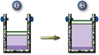
HW #4, P6 - Isobaric Expansion of R-134a - 6 pts
A piston-and-cylinder device with a set of stops contains 10 kg of R-134a. Initially, 8.0 kg of the refrigerant is in the liquid phase and the temperature is -8.0oC. Now, heat is transferred slowly into the refrigerant until the piston hits the stops. At this point, the volume is 400 L. Determine:
a.) The temperature of the R-134a when the piston reaches the stops.
b.) The boundary work done during this expansion process.
c.) The heat transfer during this expansion process.
d.) Show this process on a PV Diagram.

a.) The temperature of the R-134a when the piston reaches the stops.
b.) The boundary work done during this expansion process.
c.) The heat transfer during this expansion process.
d.) Show this process on a PV Diagram.
HW #4, P7 - 1st Law Analysis of Steam in a Closed System - 4 pts
As shown in the figure below, 5.0 kg of steam contained within a piston-and-cylinder device undergoes an expansion from state 1 where the specific internal energy is 2709.9 kJ/kg to state 2 where the specific internal energy is 2659.6 kJ/kg. During the process, there heat transfer to the steam with a magnitude of 80 kJ. Also, a paddle wheel transfers energy to the steam by work in the amount of 18.5 kJ. There is no significant change in the kinetic or gravitational potential energies of the steam. Determine the work done by the steam on the piston during the process in kJ.


HW #4, P8 - Power Plant Efficiency - 3 pts
A power cycle receives energy by heat transfer from the combustion of fuel at a rate of 300 MW. The thermal efficiency of the cycle is 33%.
a.) Determine the net rate at which power is developed in MW.
b.) For 8000 hours of operation annually, determine the net work output in kW-h/yr.
c.) Evaluating the net work output at $0.08 per kW-h, determine the value of the net work in $/yr.
a.) Determine the net rate at which power is developed in MW.
b.) For 8000 hours of operation annually, determine the net work output in kW-h/yr.
c.) Evaluating the net work output at $0.08 per kW-h, determine the value of the net work in $/yr.
HW #4, P9 - Work, Heat and COP in a Refrigeration Cycle - 2 pts
A refrigeration cycle operates as shown in the figure, with a coefficient of performance of 2.5. For the cycle, QH = 2000 kJ. Determine QC and Wcycle in kJ.
HW #4, P10 - Heat Pump COP and Monthly Operating Cost - 2 pts
A heat pump cycle whose coefficient of performance is 2.5 delivers energy by heat transfer to a home at a rate of 20 kW.
a.) Determine the net power required to operate the heat pump in kW.
b.) Evaluating electricity at $0.08 per kW-h, determine the cost of electricity in a month when the heat pump operates for 200 hours.
a.) Determine the net power required to operate the heat pump in kW.
b.) Evaluating electricity at $0.08 per kW-h, determine the cost of electricity in a month when the heat pump operates for 200 hours.
Thursday, April 05, 2007
Ch 3 - Anything Except HW
Please post any questions or discussion related to this problem as comments on this message. Feel free to answer other students' questions. I will check the blog M-F and once on the weekend.
Dr. B
Dr. B
HW #3, P1 - Steam NIST / TFT Fundamentals - 2 pts
Complete the following table for water using either the NIST Webbook or the Thermal/Fluids Toolbox (TFT) Excel plug-in.
T (oC) P (kPa) H (kJ/kg) x (kg vap/kg) Phase Description
a.) P = 200 kPa, x = 0.7 kg vap/kg
b.) T = 140oC , H = 1800 kJ/kg
c.) P = 950 kPa, x = 0 kg vap/kg
d.) T = 80oC, P = 500 kPa
e.) P = 800 kPa, H = 3161.7 kJ/kg
T (oC) P (kPa) H (kJ/kg) x (kg vap/kg) Phase Description
a.) P = 200 kPa, x = 0.7 kg vap/kg
b.) T = 140oC , H = 1800 kJ/kg
c.) P = 950 kPa, x = 0 kg vap/kg
d.) T = 80oC, P = 500 kPa
e.) P = 800 kPa, H = 3161.7 kJ/kg
HW #3, P2 - R-134a NIST/TFT Fundamentals - 2 pts
Complete the following table for R-134a using either the NIST Webbook or the Thermal/Fluids Toolbox (TFT) Excel plug-in.
T(oF) P(psia) U(Btu/lbm) x(lbm vap/lbm) Phase Description
a.) P = 80 psia, U = 126 Btu/lbm
b.) T = 15oF, x = 0.6 lbm vap/lbm
c.) T = 10oF, P = 70 psia
d.) P = 180 psia, U = 224 Btu/lbm
e.) T = 110oF, x = 1.0 lbm vap/lbm
T(oF) P(psia) U(Btu/lbm) x(lbm vap/lbm) Phase Description
a.) P = 80 psia, U = 126 Btu/lbm
b.) T = 15oF, x = 0.6 lbm vap/lbm
c.) T = 10oF, P = 70 psia
d.) P = 180 psia, U = 224 Btu/lbm
e.) T = 110oF, x = 1.0 lbm vap/lbm
HW #3, P3 - Determining DH Using Heat Capacity Polynomials - 6 pts
Determine the change in the specific internal energy of nitrogen (N2), in kJ/kg, as it is heated from 600 to 1500 K, using:
a.) The empirical specific heat equation (Shomate Equation) from the NIST Website.
b.) "The CoV value at the average temperature.
(Use the heat capacity polynomial to determine this CoV value.)
c.) The CoV value at room temperature, 25oC.
(Use the heat capacity polynomial to determine this CoV value.)
HW #3, P4 - Determining DU Using Heat Capacity Polynomials - 6 pts
Determine the change in the specific internal energy of hydrogen (H2), in kJ/kg, as it is heated from 400 to 1000 K, using:
a.) The empirical specific heat equation (Shomate Equation) from the NIST Website.
b.) The CoV value at the average temperature.
(Use the heat capacity polynomial to determine this CoV value.)
c.) The CoV value at room temperature, 25oC.
(Use the heat capacity polynomial to determine this CoV value.)
HW #3, P5 - Clapeyron & Clausius-Clapeyron Equations - 6 pts
Estimate the latent heat of vaporization, in Btu/lbm, of ammonia at -10oF using:
a.) The Clapeyron Equation
b.) The Clausius-Clapeyron Equation
c.) The ammonia tables
a.) The Clapeyron Equation
b.) The Clausius-Clapeyron Equation
c.) The ammonia tables
HW #3, P6 - Hypothetical Process Paths and the Latent Heat of Vaporization - 8 pts
Use the hypothetical process path shown here to help you determine the change in enthalpy in Joules for 20.0 g of heptane (C7H16) as it changes from a saturated liquid at 300 K to a temperature of 370 K and a pressure of 58.7 kPa. Calculate the DH for each step in the path. Do not use tables of thermodynamic properties, except to check your answers. Instead, use the Antoine Equation to estimate the heat of vaporization of heptane at 300 K. Use the average heat capacity of heptane gas over the temperature range of interest.
Assume heptane gas is an ideal gas at the relevant temperatures and pressures.

Assume heptane gas is an ideal gas at the relevant temperatures and pressures.

Subscribe to:
Posts (Atom)