Tuesday, May 22, 2007
HW #9, P1 - Brayton Cycle with Variable Heat Capacities - 6 pts
A gas turbine power plant operates on the basic Brayton Cycle. Air is the working fluid and the cycle delivers 15 MW of power. The minimum and maximum temperatures in the cycle are 310 K and 900 K, respectively. The air pressure at the compressor outlet is 8 times the pressure at the compressor inlet. Assuming an isentropic efficiency of 80% for the compressor and 86% for the turbine, determine the mass flow rate of air through the cycle. Assume that air behaves as an ideal gas, but do not assume that the heat capacities of the air are constants.
HW #9, P2 - Brayton Cycle with Regeneration - 8 pts
A Brayton Cycle with Regeneration using air as the working fluid has a pressure ratio of 7. The minimum and maximum temperatures in the cycle are 310 K and 1150 K. Assuming an isentropic efficiency of 75% for the compressor and 82% for the turbine and an efffectiveness of 65% for the regenerator, determine...
a.) The temperature of the turbine effluent.
b.) The net work output, in kJ/kg of air flowing through the system.
c.) The thermal efficiency of the cycle.
a.) The temperature of the turbine effluent.
b.) The net work output, in kJ/kg of air flowing through the system.
c.) The thermal efficiency of the cycle.
HW #9, P3 - Effect of Turbine Feed T on Rankine Cycle Efficiency - 6 pts
Steam enters the turbine of a basic Rankine power cycle at a pressure of 10 MPa and a temperature T2, and expands adiabatically to 6 kPa. The isentropic turbine efficiency is 85%. Saturated liquid water leaves the condenser at 6 kPa and the isentropic pump efficiency is 82%.
a.) For T2 = 580oC, determine the quality of the turbine effluent and the thermal efficiency of the cycle.
b.) Plot the quality of the turbine effluent and the thermal efficiency of the cycle for values of T2 ranging from 580oC to 700oC at 10oC increments.
a.) For T2 = 580oC, determine the quality of the turbine effluent and the thermal efficiency of the cycle.
b.) Plot the quality of the turbine effluent and the thermal efficiency of the cycle for values of T2 ranging from 580oC to 700oC at 10oC increments.
HW #9, P4 - Special Rankine Cycle with Reheat and Regeneration - 8 pts
A power plant operates on a regenerative vapor power cycle with one closed feedwater heater. Steam enters the high-pressure turbine at 120 bar and 520oC and expands to 10 bar, where some of the steam is extracted and diverted to a closed feedwater heater. Condensate leaves the feedwater heater as a saturated liquid at 10 bar and then passes through an expansion valve before it is combined with the effluent from the low-pressure turbine. This combined stream flows to the condenser. The boiler feed leaves the feedwater heater at 120 bar and 170oC. The condenser pressure is 0.06 bar. Each turbine stage has an isentropic efficiency of 82%. The pump is essentially isentropic.

Determine...
a.) The thermal efficiency of the cycle.
b.) The mass flow rate of water/steam through the boiler in kg/h. if the net power output of the cycle is 320 MW.
Determine...
a.) The thermal efficiency of the cycle.
b.) The mass flow rate of water/steam through the boiler in kg/h. if the net power output of the cycle is 320 MW.
HW #9, P5 - Helium Gas Refrigeration Cycle - 6 pts
A gas refrigeration cycle with a pressure ratio of 3 uses helium as the working fluid. The temperature of the helium is -10oC at the compressor inlet and 50oC at the turbine inlet. Assuming adiabatic efficiencies of 82% for both the turbine and the compressor, determine...
a.) The minimum temperature in the cycle.
b.) The coefficient of performance.
c.) The mass flow rate of the helium in kg/s for a refrigeration load of 12 kW.
a.) The minimum temperature in the cycle.
b.) The coefficient of performance.
c.) The mass flow rate of the helium in kg/s for a refrigeration load of 12 kW.
HW #9, P6 - Ammonia Cascade Refrigeration Cycle - 8 pts
The diagram shows a two-stage, vapor-compression refrigeration system that uses ammonia as the working fluid. The system uses a flash drum to achieve intercooling. The evaporator has a refrigeration capacity of 30 tons and produces a saturated vapor effluent at -20oF. In the first compressor stage, the refrigerant is compressed adiabatically to 80 psia, which is the pressure in the mixer. Saturated vapor at 80 psia enters the second compressor stage and is compressed adiabatically to 250 psia. Each compressor stage has an isentropic efficiency of 85%. Ther are no significant pressure drops as the refrigerant passes through the heat exchangers. Saturated liquid enters each expansion valve.
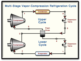
Determine...
a.) The mass flow rate of R-134a through each compressor in lbm/h.
b.) The power input to each compressor in Btu/h.
c.) The coefficient of performance of the cycle.

Determine...
a.) The mass flow rate of R-134a through each compressor in lbm/h.
b.) The power input to each compressor in Btu/h.
c.) The coefficient of performance of the cycle.
HW #9, P7 - Vapor-Compression Heat Pump - 6 pts
A vapor-compression heat pump uses R-134a as the working fluid. The refrigerant enters the compressor at 2.4 bar and 0oC at a volumetric flow rate of 0.60 m3/min. Compression is adiabatic to 9 bar and 60oC and saturated liquid leaves the condenser at 9 bar. Determine...
a.) The power input to the compressor in kW.
b.) The heating capacity of the heat pump in kW.
c.) The coefficient of performance.
d.) The isentropic compressor efficiency.
a.) The power input to the compressor in kW.
b.) The heating capacity of the heat pump in kW.
c.) The coefficient of performance.
d.) The isentropic compressor efficiency.
Monday, May 21, 2007
Monday, May 14, 2007
HW #8, P1 - Back-Work Ratio of a Steam Power Cycle - 4 pts
Consider a steam power plant that operates between the pressure limits of 10 MPa and 20 kPa. Steam enters the pump as a saturated liquid and leaves the turbine as a saturated vapor. Determine the back work ratio (BWR is the ratio of the work delivered by the turbine to the work consumed by the pump). Assume the entire cycle to be reversible and the heat losses from the pump and the turbine to be negligible.
HW #8, P2 - Isentropic Efficiency of a CO2 Compressor - 4 pts
Carbon dioxide enters an adiabatic compressor at 100 kPa and 300 K at a rate of 2.2 kg/s and exits at 600 kP and 450 K. Neglecting changes in kinetic and potential energies, determine the isentropic efficiency of the compressor.
HW #8, P3 - Analysis of an R-134a Compressor - 5 pts
R-134a enters an adiabatic compressor as saturated vapor at 120 kPa at a rate of 0.30 m3/min and exits at 1.0 MPa. If the isentropic efficiency of the compresor is 80%, determine…
a.) The temperature of the R-134a at the outlet of the compressor.
b.) The power input to the compressor in kW.
c.) Show the process path on a TS Diagram that includes the two phase envelope and all relevant isobars.
a.) The temperature of the R-134a at the outlet of the compressor.
b.) The power input to the compressor in kW.
c.) Show the process path on a TS Diagram that includes the two phase envelope and all relevant isobars.
HW #8, P4 - Polytropic Compression of N2 with Varying delta - 6 pts
Nitrogen gas is compressed from 80 kPa and 27oC to 480 kPa by a 10 kW compressor. Determine the mass flow rate of nitrogen through the compressor assuming the compression process is …
a.) Isentropic, gamma = 1.4
b.) Polytropic with delta = 1.3
c.) Isothermal
d.) Ideal, two-stage polytropic with delta = 1.3
a.) Isentropic, gamma = 1.4
b.) Polytropic with delta = 1.3
c.) Isothermal
d.) Ideal, two-stage polytropic with delta = 1.3
HW #8, P5 - Lost Work in a Heat Exchanger - 4 pts
A well-insulated shell-and-tube heat exchanger is used to heat water (CP = 4.18 kJ/kg-K) in the tubes from 20oC to 70oC at a rate of 4.5 kg/s. Heat is supplied by hot oil (CP = 2.30 kJ/kg-K) that enters the shell side at 170oC at a rate of 10 kg/s. Disregarding any heat loss from the heat exchanger, determine...

a.) The exit temperature of the oil.
b.) The rate of entropy generation in the heat exchanger.
c.) The rate at which work is lost due to the irreversible nature of heat transfer in this process in kW. Assume the surroundings are at 20oC.

a.) The exit temperature of the oil.
b.) The rate of entropy generation in the heat exchanger.
c.) The rate at which work is lost due to the irreversible nature of heat transfer in this process in kW. Assume the surroundings are at 20oC.
HW #8, P6 - Entropy Change, Heat Transfer and Irreversibilities - 3 pts
A closed system undergoes a process in which work is done on the system and heat transfer Q occurs only at temperature Tb. For each case listed below, determine whether the entropy change of the system is positive, negative, zero or indeterminate (you cannot tell for sure from the given information).
a.) Internally reversible process with Q > 0.
b.) Internally reversible process with Q = 0.
c.) Internally reversible process with Q < 0.
d.) Internal irreversibilities present with Q > 0.
e.) Internal irreversibilities present with Q = 0.
f.) Internal irreversibilities present with Q < 0.
a.) Internally reversible process with Q > 0.
b.) Internally reversible process with Q = 0.
c.) Internally reversible process with Q < 0.
d.) Internal irreversibilities present with Q > 0.
e.) Internal irreversibilities present with Q = 0.
f.) Internal irreversibilities present with Q < 0.
HW #8, P7 - Entropy Generation and Lost Work in a Nozzle - 5 pts
Oxygen, O2, enters a nozzle operating at steady-state at 3.8 MPa, 387oC and 10 m/s. At the nozzle exit, the conditions are 150 kPa, 37oC and 790 m/s.
a.) For a system that encloses the nozzle only, determine the heat transfer (kJ/kg) and the change in specific entropy (kJ/kg-K), both per kg of oxygen flowing through the nozzle. What additional information would be required to evaluate the rate of entropy production in this process ?
b.) Using an enlarged system boundary that includes the nozzle and a portion of its immediate surroundings, evaluate the rate of entropy generation (kJ/kg-K) and the rate of lost work (kJ/kg), both per kg of oxygen flowing through the nozzle. Assume that heat exchange at the enlarged system boundary takes place at the ambient temperature, 20oC.
Treat O2 as an ideal gas with variable heat capacities. Verify that the ideal gas assumption is valid.
HW #8, P8 - Lost Work in an Air Compressor and HEX - 6 pts
Air flows through the compressor and heat exchanger in the system shown in the diagram. A separate liquid water stream (CP,W = 4.18 kJ/kg-K) also flows through the heat exchanger. The data given on the diagram are based on steady-state operation. Consider the air to be an ideal gas and neglect heat exchange with the surroundings as well as changes in kinetic and potential energies. Determine...

a.) The compressor power requirement in kW and the mass flow rate of the cooling water in kg/s.
b.) The rate of entropy generation in kW/K and the rate at which work is lost in kW for the compressor. Assume the temperature of the surroundings is 300 K.
c.) The rate of entropy generation in kW/K and the rate at which work is lost in kW for the heat exchanger. Assume the temperature of the surroundings is 300 K.
Subscribe to:
Posts (Atom)